
Phase change temperature control device for electronic heating components and manufacturing method thereof

A technology for heating components and temperature control devices, which is applied in cooling/ventilation/heating renovation, heat storage equipment, heat exchanger types, etc. line, avoid damaging effects

Active Publication Date: 2016-09-07
SHANGHAI RADIO EQUIP RES INST
View PDF4 Cites 0 Cited by
  • Summary
  • Abstract
  • Description
  • Claims
  • Application Information

AI Technical Summary

Problems solved by technology

However, its limitation is: when the heat flux density of electronic equipment exceeds 0.8W / cm 2 When the natural heat dissipation (cooling) has been unable to meet the corresponding cooling
However, its limitation is that the entire forced air cooling system requires a large volume, and its cooling capacity will be greatly reduced in high-altitude environments and environments with thin air and low air pressure
This method is difficult to implement and the economy is not high

Method used


Image

  • Phase change temperature control device for electronic heating components and manufacturing method thereof
  • Phase change temperature control device for electronic heating components and manufacturing method thereof
  • Phase change temperature control device for electronic heating components and manufacturing method thereof

Examples


Embodiment Construction

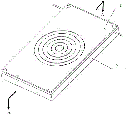
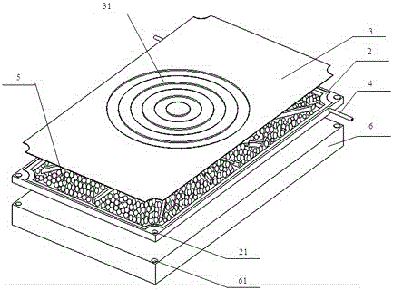
[0034] The following combination Figure 1 to Figure 5 , a preferred embodiment of the present invention is described in detail.

[0035] like Figure 1 ~ Figure 3 As shown, the phase change temperature control device 1 of the electronic heating component provided by the present invention controls the temperature of the electronic heating component 6, and specifically includes: a housing 2, which has an inner cavity, and the housing 2 The outer bottom surface is arranged in close contact with the electronic heating component 6; the cover plate 3 is welded and arranged on the top of the housing 2, so that the inner cavity of the housing 2 becomes a closed space; the auxiliary vacuum tube 4 , which are respectively welded on both sides of the housing 2 and respectively pass through the side walls of the housing 2 ;

[0036]Each corner of the housing 2 is provided with a first screw hole 21, and each corner of the electronic heating component 6 is respectively provided with a s...


PUM


Abstract

The invention relates to a phase change temperature control device of an electronic heating assembly. The phase change temperature control device comprises a shell, a cover plate, vacuum pumping auxiliary tubes and a phase change energy storage material. The shell is provided with an inner cavity, and a rib-shaped structure which is arranged in an annular scattering array mode is arranged on the surface of the bottom of the inner cavity. The outer bottom surface of the shell is arranged to be attached to the electronic heating assembly. The cover plate is welded on the top of the shell, and accordingly the inner cavity of the shell is turned into a confined space. The vacuum pumping auxiliary tubes are welded on the two sides of the shell and penetrate through the side wall of the shell. The phase change energy storage material is packaged in the inner cavity of the shell. The phase transformation point of the phase change energy storage material is lower than the highest normal working temperature of the electronic heating assembly. The cover plate is further provided with a size compensable structure. According to the phase change temperature control device of the electronic heating assembly, based on the characteristic that the phase change energy storage material enables the temperature to be controlled within a certain range, the phase change energy storage material is packaged in the phase change temperature control device in a sealing mode, and thus the damage to the phase change temperature control device due to the fact that the size of the phase change energy storage material is expanded after phase change can be avoided through the size compensable structure.

Description

technical field [0001] The invention relates to a phase-change temperature control device for electronic heating components and a manufacturing method thereof, more specifically, a phase-change temperature control device suitable for electronic heating components in a narrow space and a manufacturing method thereof, belonging to electronic devices The technical field of heat dissipation and thermal management. Background technique [0002] High-power electronic components will generate a lot of heat when they work. If the heat is not dissipated in time or managed properly, the performance of electronic components will be seriously affected. Especially in some systems, multiple electronic components need to work together, and there are strict requirements on the temperature consistency of each electronic component. Improper temperature control will affect the performance of the system. In severe cases, the electronic components may be burned and the system may not work proper...

Claims


Application Information

Patent Timeline
Patent Type & Authority Patents(China)
IPC IPC(8): H05K7/20F28D20/02
CPCY02E60/14
Inventor 彭思平王燕玲杨鑫鑫顾网平皋利利
Owner SHANGHAI RADIO EQUIP RES INST
Learn More