
High-performance pure electric motor sweeper

A pure electric, sweeper technology, used in cleaning methods, road cleaning, construction, etc., can solve the problems of low cleaning efficiency, increase labor intensity of workers, inconvenient garbage collection operations, etc., and achieve the effect of convenient operation and high cleaning efficiency.

Pending Publication Date: 2022-04-29
安徽丰源车业有限公司
View PDF8 Cites 0 Cited by
  • Summary
  • Abstract
  • Description
  • Claims
  • Application Information

AI Technical Summary

Problems solved by technology

[0004] 1. The traditional way of cleaning the road surface is generally manual cleaning, which not only has low cleaning efficiency, but also increases the labor intensity of workers;
[0005] 2. The existing road sweepers on the market are inconvenient to collect garbage, which reduces the practicality of pulling the sweeper

Method used


Image

  • High-performance pure electric motor sweeper
  • High-performance pure electric motor sweeper
  • High-performance pure electric motor sweeper

Examples


Embodiment 1

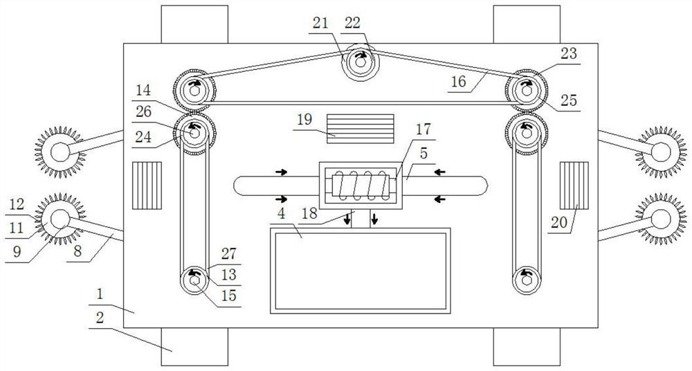
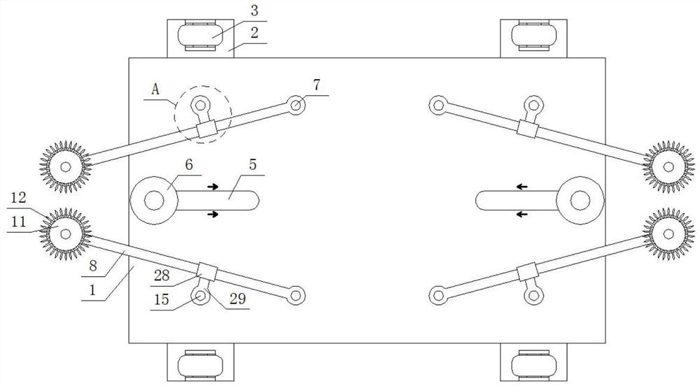
[0027] Such as Figure 1-4 As shown, a high-performance pure electric sweeper includes a base plate 1, a pair of symmetrical connecting plates 2 are fixed on the front and rear sides of the base plate 1, and a roller bracket is installed on the bottom surface of each connecting plate 2, and each roller Rollers 3 are all installed on the support. The setting of the roller 3 increases the convenience of moving the whole device. The top surface of the base plate 1 is evenly provided with four rotating shafts 15, each rotating shaft 15 runs through the bottom surface of the base plate 1 and is connected to the base plate 1 in rotation, and the bottom surface of each rotating shaft 15 is fixedly equipped with a swing guide rod 29, each A cleaning assembly is arranged between the swing guide rod 29 and the base plate 1; the cleaning assembly includes a fixed shaft 7, which is arranged on the bottom surface of the base plate 1 and fixedly connected with the base plate 1, and the bot...

Embodiment 2

[0031] Such as Figure 1-4 Shown, under the situation that other parts are all identical with embodiment 1, the difference between this embodiment and embodiment 1 is:

[0032] The dust suction assembly includes a dust suction pump 17, which is installed on the top surface of the base plate 1. The model of the dust suction pump 17 is XWB-530, and the dust suction pump 17 is electrically connected to the first battery board 19 through a power line. The dust inlet ends of the left and right ends of the dust suction pump 17 are connected and fixed with a dust suction pipe 5, and the bottom of each dust suction pipe 5 runs through the bottom plate 1 and is fixedly connected with the bottom plate 1. The bottom ends are all communicated with and fixedly provided with a dust collection tray 6, the end of the dust discharge end of the dust collection pump 17 is connected with and fixedly provided with a dust discharge pipe 18, and the front of the dust collection pump 17 is provided w...


PUM


Abstract

The high-performance pure electric sweeping vehicle comprises a bottom plate, four rotating shafts are evenly arranged on the top face of the bottom plate, each rotating shaft penetrates through the bottom face of the bottom plate and is rotationally connected with the bottom plate, a swing guide rod is fixedly arranged on the bottom face of each rotating shaft, and a sweeping assembly is arranged between each swing guide rod and the bottom plate; the top end of each rotating shaft located in the front is fixedly provided with a first belt pulley, the top end of each rotating shaft located in the rear is fixedly provided with a driven belt pulley, and transmission assemblies are arranged between the two driven belt pulleys and the bottom plate. A driving gear is arranged below each driven belt wheel, each driving gear is arranged on the corresponding rotating shaft in a sleeving mode and fixedly connected with the rotating shaft, a connecting assembly is arranged between each driving gear and the corresponding first belt wheel, and a dust collection assembly is arranged on the bottom plate. The road surface cleaning device not only facilitates road surface cleaning operation, but also facilitates automatic collection of dust, and is easy to operate and beneficial to popularization.

Description

technical field [0001] The invention relates to the technical field of electric cleaning vehicles, in particular to a high-performance pure electric cleaning vehicle. Background technique [0002] Sweeper is that collection road cleaning, garbage reclamation and transportation are the new and efficient cleaning equipment of one. It is a vehicle type equipment suitable for all-round cleaning of factories, highways, parks, squares and other road surfaces. [0003] Existing cleaning vehicles on the market have the following problems: [0004] 1. The traditional way of cleaning the road surface is generally manual cleaning, which not only has low cleaning efficiency, but also increases the labor intensity of workers; [0005] 2. It is inconvenient to collect garbage in the existing road sweeping vehicles on the market, thereby reducing the practicability of pulling the sweeping vehicles. Contents of the invention [0006] The object of the present invention is to provide a ...

Claims


Application Information

Patent Timeline
Patent Type & Authority Applications(China)
IPC IPC(8): E01H1/08
CPCE01H1/0836E01H1/0845
Inventor 宣洪祥李子军
Owner 安徽丰源车业有限公司
Learn More