Supercharge Your Innovation With Domain-Expert AI Agents!

Hot oil pump with oil-gas multi-stage separation mechanism and method

A multi-stage separation and thermal oil pump technology, applied in separation methods, dispersed particle separation, chemical instruments and methods, etc., can solve problems such as oil cracking, mechanical seal damage, thermal oil pump mechanical seal damage, etc.

Inactive Publication Date: 2022-04-29
王少华
View PDF0 Cites 0 Cited by
  • Summary
  • Abstract
  • Description
  • Claims
  • Application Information

AI Technical Summary

Problems solved by technology

[0002] The hot oil pump is an ideal hot oil circulation pump or heat transfer pump. It is an ideal matching pump for heat exchange equipment. There are still big defects in the hot oil pump when it is used for a long time, the most important is the high temperature of the oil. And the high-speed rotation of the pump shaft will cause cracking of the oil, and the gaseous hydrocarbon components with low boiling points will accumulate in the pump body and cover the entire pump shaft, which will cause damage to the mechanical seal of the thermal oil pump. For this reason, the existing thermal oil pump It is equipped with an oil-gas separation system to prevent the gas from remaining in the pump shaft cavity for a long time, resulting in damage to the mechanical seal
[0003] Its existing thermal oil pump oil-air separation mechanism collects and separates the air mixed in the oil flowing into the pump shaft cavity, and then transports the air to the impeller cavity through the oil circulation, so that the air follows the oil out of the impeller cavity, so that The air will not remain in the pump shaft chamber, but because the oil outlet and the oil inlet of the thermal oil pump are circulated, after the air is discharged through the oil outlet, part of the air will still follow the oil inlet into the impeller chamber and the pump shaft chamber Inside, the air is not really discharged from the pump body. Every time the air enters the pump shaft cavity, there is still a phenomenon that the oil squeezes the air to make it burst and cause damage to the mechanical seal. For this reason, we propose a Thermal oil pump with oil-gas multi-stage separation mechanism and method

Method used


Image

  • Hot oil pump with oil-gas multi-stage separation mechanism and method
  • Hot oil pump with oil-gas multi-stage separation mechanism and method
  • Hot oil pump with oil-gas multi-stage separation mechanism and method

Examples


Embodiment 1

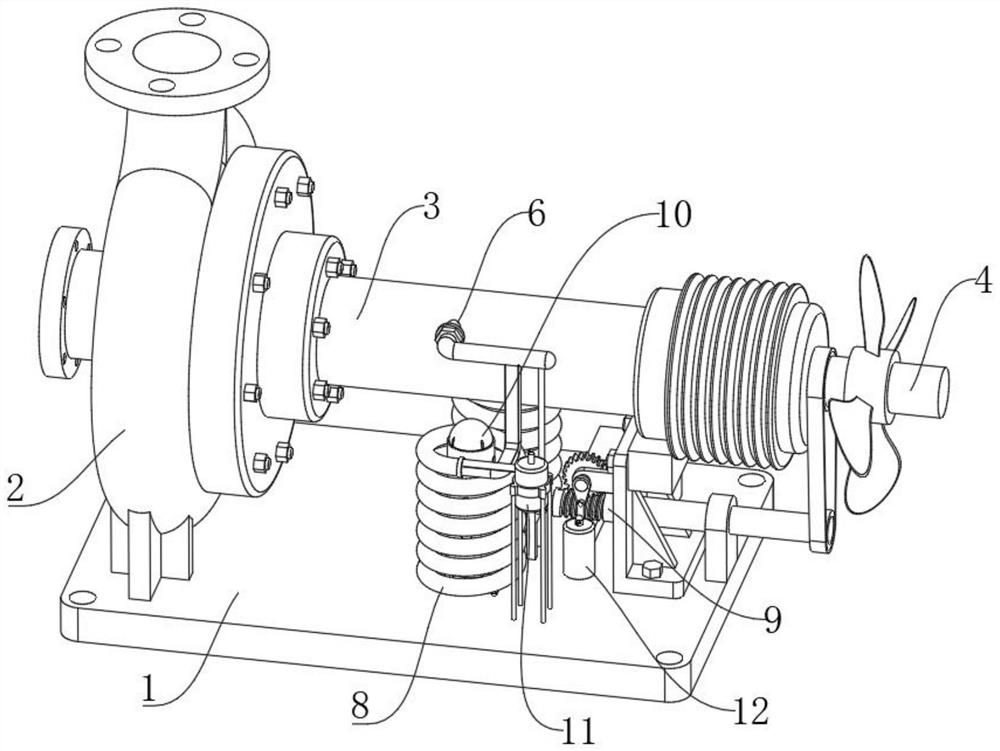
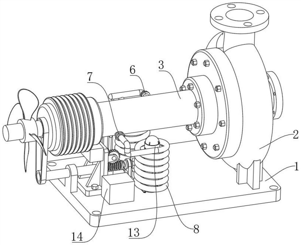
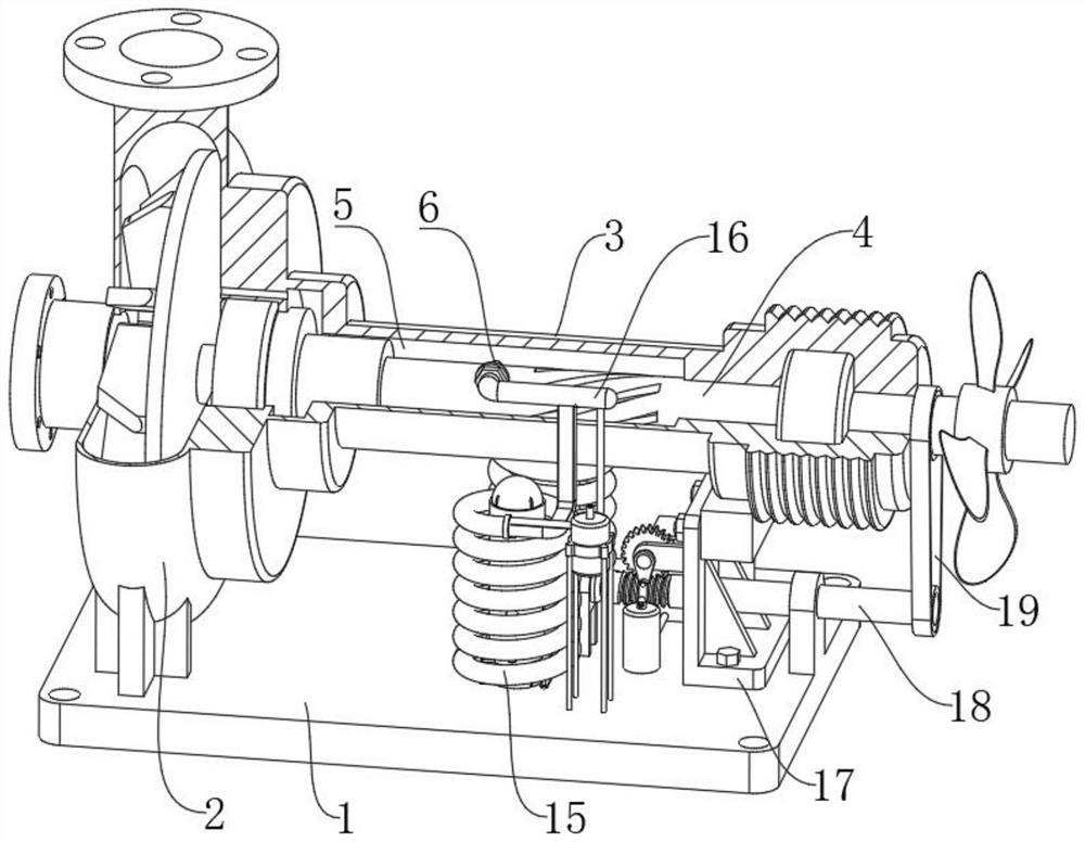
[0033] see figure 1 and figure 2 , a thermal oil pump with an oil-gas multi-stage separation mechanism in the figure, including a base 1, the upper end of the base 1 is fixedly installed with an impeller shell 2 and a sealing sleeve 3, and the impeller shell 2 and the sealing sleeve 3 communicate with each other, and the sealing shaft The inner side of the sleeve 3 is embedded with a transmission shaft 4, and a sleeve cavity 5 is opened between the sealing sleeve 3 and the transmission shaft 4, and fan blades are fixedly installed on the outer surface of the transmission shaft 4, and the sealing sleeve 3 and the base 1 are fixed. Mounting frame 17 is installed, and the front end of sealing shaft sleeve 3 is equipped with connecting pipe one 6, and the rear end of sealing shaft sleeve 3 is equipped with connecting pipe two 7, connecting pipe one 6 and connecting pipe two 7 are all connected with the shaft The casing cavity 5 is connected; the exhaust mechanism 8, which can re...

Embodiment 2

[0044] see Figure 7 In this embodiment, the embodiment 1 is further described. The cooling mechanism 10 includes two sets of fixed columns 39 installed inside the oil guide pipe 15, and the fixed columns 39 are fixedly connected to the base 1, and guide rails are fixedly installed between the two sets of fixed columns 39. Flow pipe 40, seal pipe 57 is installed on the inboard of fixed post 39, and the outside of seal pipe 57 is installed with several groups of one-way valve nozzles 58 through through pipe, and one-way valve nozzle 58 is embedded in the inboard of fixed post 39, and guide tube The two ends of 40 correspond to the bottoms of two groups of sealed pipes 57, and the outside of the guide pipe 40 is equipped with a conveying member 12. Under the action of the conveying member 12, the one-way valve nozzle 58 can spray alcohol solution on the surface of the oil guide pipe 15. , to lower the temperature of the oil inside the sleeve cavity 5 .

[0045] see Figure 7 a...

Embodiment 3

[0049] see Figure 7 and Figure 9 , the implementation mode is further described for other embodiments, the outer side of the fixed column 39 is equipped with a protective piece 13, and the protective piece 13 includes a protective sleeve 55 that is movably socketed on the outer side of the fixed column 39, and the inner wall of the protective sleeve 55 is fixedly installed with a limit strip, And the limit bar and the fixed column 39 are movably fitted, the outer side of the protective cover 55 is provided with several groups of through holes 56, the bottom of the protective cover 55 is fixedly installed with the limit plate 41, and the two sets of limit plates 41 are fixedly installed with a connection Frame 42, the upper end of base 1 is fixedly installed with deceleration disk 53 through the platform, and the input shaft of worm screw 18 and deceleration disk 53 is fixedly connected, and the output end of deceleration disk 53 is fixedly installed with cam 54, and the uppe...


PUM


Abstract

The invention discloses a hot oil pump with an oil-gas multi-stage separation mechanism and a method, relates to the technical field of hot oil pumps, and solves the problem that an existing hot oil pump cannot effectively discharge air in oil liquid, the hot oil pump comprises a base, and an impeller shell and a sealing shaft sleeve are fixedly mounted at the upper end of the base. In the starting process of the hot oil pump, high-speed rotation of the transmission shaft can apply pressure to oil in the shaft sleeve cavity, so that the oil circularly flows through the oil guide pipe, and an oil-gas mixture can be discharged into the collecting barrel through the isolation plate in the flowing process; oil flows back to the interior of the shaft sleeve cavity through the connecting pipe, air is exhausted through the exhaust pipe, when the transmission shaft is started, the conveying piece can be started through the transmission mechanism, the conveying piece intermittently inputs an alcoholic solution into the sealing pipe and sprays the alcoholic solution out through the one-way valve spray head, and hot oil in the oil guide pipe can be cooled.

Description

technical field [0001] The invention relates to the technical field of thermal oil pumps, in particular to a thermal oil pump with an oil-gas multi-stage separation mechanism and a method thereof. Background technique [0002] The hot oil pump is an ideal hot oil circulation pump or heat transfer pump. It is an ideal supporting pump for heat exchange equipment. There are still big defects in the hot oil pump when it is used for a long time, the most important is the high temperature of the oil. And the high-speed rotation of the pump shaft will cause oil cracking, and the gaseous hydrocarbon components with low boiling points will accumulate in the pump body and cover the entire pump shaft, which will cause damage to the mechanical seal of the thermal oil pump. For this reason, the existing thermal oil pump There is an oil-gas separation system installed to prevent the gas from remaining in the pump shaft cavity for a long time, resulting in damage to the mechanical seal. ...

Claims


Application Information

Patent Timeline
Patent Type & Authority Applications(China)
IPC IPC(8): F04D29/00F04D29/58B01D45/08
CPCF04D29/007F04D29/586B01D45/08
Inventor 王少华其他发明人请求不公开姓名
Owner 王少华
Features
  • R&D
  • Intellectual Property
  • Life Sciences
  • Materials
  • Tech Scout
  • Unparalleled Data Quality
  • Higher Quality Content
  • 60% Fewer Hallucinations
Learn More