Isolation switch with arc extinguishing structure and moving contact assembly of isolation switch

An isolating switch and moving contact technology, which is applied to air switch parts, electrical switches, electrical components, etc., can solve the problems of insufficient arc extinguishing ability of the isolating switch, lack of high-parameter bus switching current switching ability, etc. Blocking effect, solving the lack of arc extinguishing ability, and promoting the effect of rapid extinguishing

Pending Publication Date: 2022-04-29
PINGGAO GRP +1
View PDF0 Cites 0 Cited by
  • Summary
  • Abstract
  • Description
  • Claims
  • Application Information

AI Technical Summary

Problems solved by technology

[0005] The purpose of the present invention is to provide an isolating switch with an arc extinguishing structure to solve the technical problems that the conventiona

Method used


Image

  • Isolation switch with arc extinguishing structure and moving contact assembly of isolation switch
  • Isolation switch with arc extinguishing structure and moving contact assembly of isolation switch
  • Isolation switch with arc extinguishing structure and moving contact assembly of isolation switch

Examples


Embodiment 1

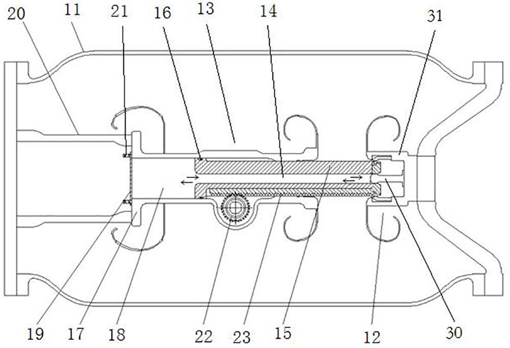
[0068] In this embodiment, the isolating switch with arc extinguishing structure is used as a bypass isolating switch for UHV series compensation, such as figure 1 As shown, the isolating switch with arc extinguishing structure includes a housing 11, a transmission mechanism, a moving contact assembly 13 arranged in the housing 11, and a static end assembly 12 located in front of the moving direction of the moving contact assembly 13, and the moving contact assembly The front of the moving direction of 13 is the direction in which the moving contact assembly 13 faces the static end assembly 12 .

[0069] In this example, if figure 1 As shown, the moving contact assembly 13 includes a moving end support 17 with a guide hole 18 and a moving contact 15, an insulating support seat 20 is provided between the rear end of the moving end support 17 and the housing 11, and the moving end support 17 is fixed on the housing 11 through an insulating support base 20 . The rear end of the...

Embodiment 2

[0079] The difference between this embodiment and Embodiment 1 is that in this embodiment, the guide hole section is a blind hole, and the bottom of the blind hole forms a plugging structure.

Embodiment 3

[0081] The difference between this embodiment and Embodiment 1 is that in this embodiment, the baffle is provided with a pressure relief structure, the pressure relief structure includes a pressure relief hole arranged on the baffle, and the rear side of the baffle is provided with The cover is equipped with a guide post, and the rear of the cover is provided with a spring for elastically pressing the cover on the baffle. When the air pressure in the piston chamber overcomes the pressing force of the spring, the cover and the discharge A gap is created between the pressure holes, through which the piston chamber is depressurized.


PUM


Abstract

The invention relates to an isolating switch with an arc extinguishing structure and a moving contact assembly of the isolating switch. A moving contact assembly of the disconnecting switch comprises a moving end support with a guide hole, a moving contact is assembled in the guide hole in a guiding mode, the moving contact is provided with an inserting part used for being matched with a static arc contact on a static end assembly in an inserting mode, the rear end of the moving end support is provided with a blocking structure, and the blocking structure blocks the rear end of the guide hole so as to form a piston cavity together with the guide hole; the moving contact is in sliding sealing fit with the piston cavity to form a piston, and an airflow channel which is communicated with the inserting part and penetrates backwards is formed in the position, behind the inserting part, of the moving contact and used for enabling an opening of the inserting part to form suction airflow when the moving contact is switched on and form exhaust airflow when the moving contact is switched off. The arc is blown by suction air flow and exhaust air flow. Therefore, the electric arc between the moving contact and the static end assembly is rapidly extinguished, and the arc extinguishing capability of the isolation switch with the arc extinguishing structure in the bus switching current switching process is improved.

Description

technical field [0001] The invention relates to the technical field of isolating switches, in particular to an isolating switch with an arc extinguishing structure and a moving contact assembly of the isolating switch. Background technique [0002] The isolating switch is an important component in the high-voltage switch system. The isolating switch generally includes a housing, a moving contact assembly arranged in the housing, and a static end assembly arranged at the front end of the moving contact assembly. The moving contact assembly includes a guide hole. The moving end support is guided and slid in the guide hole to be equipped with a moving contact, and there are different driving forms of the moving contact in the prior art. For example, a rack is installed on the moving contact of the isolating switch, and the rotating gear meshes with the rack to drive the moving contact, thereby realizing closing or opening of the isolating switch. The isolating switch can also ...

Claims


Application Information

Patent Timeline
IPC IPC(8): H01H9/30H01H31/02
CPCH01H31/026H01H9/30H01H2009/348
Inventor 占小猛段晓辉孙英杰柴影辉董祥渊魏建巍谢世超高远常克歌杜迎乾贺永明李俊锋郭良超井琼琼白杨齐小虎仓韬
Owner PINGGAO GRP
Why Eureka
Try Eureka