Plywood manufacturing equipment based on dry heat method

A technology for manufacturing equipment and plywood, applied in the direction of manufacturing tools, wooden veneer joints, glue guns, etc., can solve the problems of plywood manufacturing efficiency, cumbersome operation steps, etc., to achieve manpower saving, high degree of intelligence, good adhesion combined effect

Active Publication Date: 2022-05-03
林少山
View PDF8 Cites 3 Cited by
  • Summary
  • Abstract
  • Description
  • Claims
  • Application Information

AI Technical Summary

Problems solved by technology

[0005] In order to overcome the disadvantages that the existing plywood manufacturing equipment based on the dry heat method requires staff to continuously carry out material loading and gluing work, such operation steps are relatively cumbersome and affect the production efficiency of plywood, and a new method is provided that does not require too much manual work. Plywood manufacturing equipment based on dry heat method with high operation, automation and production efficiency

Method used


Image

  • Plywood manufacturing equipment based on dry heat method
  • Plywood manufacturing equipment based on dry heat method
  • Plywood manufacturing equipment based on dry heat method

Examples


Embodiment 1

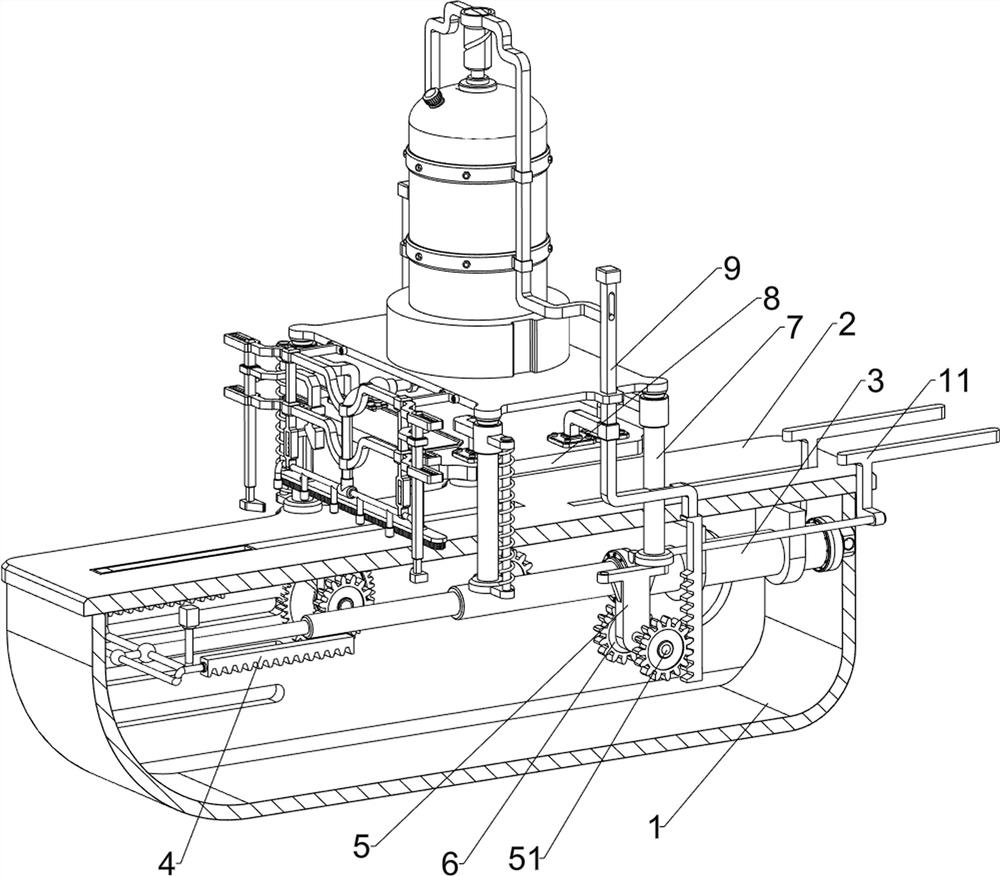
[0030] A kind of plywood manufacturing equipment based on dry heat method, refer to figure 1 with figure 2As shown, it includes a bottom plate 1, a first mounting plate 2, a multi-stage hydraulic cylinder 3, a first rack 4, a first bearing seat 5, a first rotating rod 51, a first gear 6, a mounting column 7, a pressure plate 8, The second rack 9, the feeding mechanism 10, the feeding mechanism 11 and the gluing mechanism 12, the top of the bottom plate 1 is welded with the first mounting plate 2, and the right side of the bottom of the first mounting plate 2 is provided with a multi-stage hydraulic cylinder 3. The left side of the telescopic shaft on the hydraulic cylinder 3 is symmetrically provided with a first rack 4, and the right side of the bottom of the first mounting plate 2 is symmetrically connected with a first bearing seat 5 through bolts, and the lower side of the first bearing seat 5 is provided with The first rotating rod 51, the first rotating rod 51 is conne...

Embodiment 2

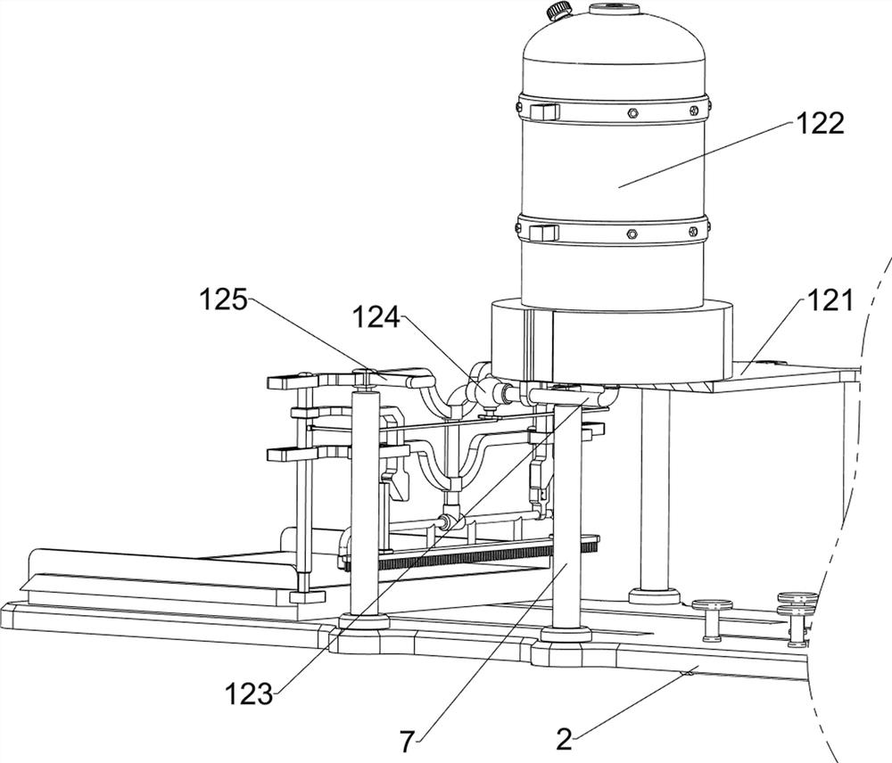
[0036] On the basis of embodiment 1, refer to figure 1 with Figure 7 As shown, also includes glue application mechanism 13, glue application mechanism 13 can make glue smear evenly on the lower plate of plywood, and glue application mechanism 13 includes the 3rd wedge block 131, the 4th spring 132, hairbrush 133 and back-moving spring 134, the inner upper part of telescopic rod 127 is equipped with a third wedge-shaped block 131, and the third wedge-shaped block 131 is slidably connected with the mounting frame 125, and the third wedge-shaped block 131 is connected with the mounting frame 125 with a fourth spring 132. The lower part of the frame 125 is slidingly provided with a brush 133, which can make the glue smear evenly, and a back-moving spring 134 is symmetrically connected between the top of the brush 133 and the mounting frame 125.

[0037] The telescopic rod 127 moves to the outside to drive the third wedge-shaped block 131 to move to the outside, and the third wed...


PUM


Abstract

The invention relates to plywood manufacturing equipment, in particular to plywood manufacturing equipment based on a dry heat method. The plywood manufacturing equipment based on the dry heat method does not need excessive manual operation and is high in automation degree and production efficiency. According to the technical scheme, the plywood manufacturing equipment based on the dry heat method comprises a bottom plate, a first mounting plate, a multi-stage hydraulic cylinder, mounting columns, a pressing plate and the like, the first mounting plate is arranged at the top of the bottom plate, the multi-stage hydraulic cylinder is arranged on the right side of the bottom of the first mounting plate, and the mounting columns are arranged on the front side and the rear side of the top of the first mounting plate in a bilateral symmetry mode; a pressing plate used for extruding the plate is slidably connected between the upper sides of the mounting columns. After raw materials for manufacturing the plywood are placed on the equipment, the plywood can be automatically manufactured by controlling the multi-stage hydraulic cylinder to work, so that the intelligent degree is high, excessive manual operation is not needed, and manpower is saved.

Description

technical field [0001] The invention relates to a plywood manufacturing equipment, in particular to a plywood manufacturing equipment based on a dry heat method. Background technique [0002] Plywood is one of the commonly used materials for furniture and is one of the three major wood-based panels. In order to reduce the gluing time of plywood and ensure product quality, plywood is usually manufactured by dry heat method when producing plywood. [0003] The existing plywood manufacturing equipment based on the dry heat method includes a bottom plate, a first mounting plate, a multi-stage hydraulic cylinder, a first rack, a first bearing seat, a first rotating rod, a first gear, a mounting column, a pressing plate and The second rack, the top of the base plate is provided with the first mounting plate, the bottom right of the first mounting plate is provided with a multi-stage hydraulic cylinder, the left side of the telescopic rod of the multi-stage hydraulic cylinder is sy...

Claims


Application Information

Patent Timeline
Patent Type & Authority Applications(China)
IPC IPC(8): B27D1/08B27G11/00
CPCB27D1/08B27G11/005
Inventor 林少山
Owner 林少山
Why Eureka
Try Eureka