A jar for oil drilling

A jar and oil technology, which is applied in the direction of drilling with vibration, can solve the problems of affecting the service life and the rapid loss of the internal components and shell of the jar, and achieve the effect of ensuring the jarring effect and improving the jarring effect.

Active Publication Date: 2022-07-01
天津合力北方能源技术有限公司
View PDF0 Cites 0 Cited by
  • Summary
  • Abstract
  • Description
  • Claims
  • Application Information

AI Technical Summary

Problems solved by technology

[0004] Most jars use up and down jarring to release the jam, but during the actual operation of the jar, the internal jar parts will cause an axial impact on the shell of the jar, which are generally rigid Impact force, long-term axial shock will cause the internal parts and shell of the jar to wear quickly, affecting its service life

Method used


Image

  • A jar for oil drilling
  • A jar for oil drilling
  • A jar for oil drilling

Examples


Embodiment

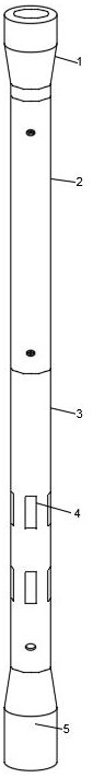
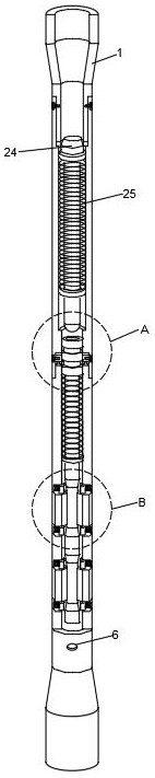
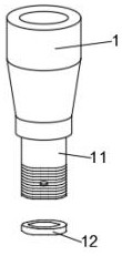
[0039] Please refer to Figure 1-Figure 10 ,in, figure 1 A schematic structural diagram of a preferred embodiment of the jar for oil drilling provided by the present invention; figure 2 A schematic diagram of the half-section structure of the jar for oil drilling provided by the present invention; image 3 It is the structural representation of the upper joint in the present invention; Figure 4 It is a schematic diagram of the structure of the installation pipe in the present invention; Figure 5 is the structural schematic diagram of the impact rod in the present invention; Image 6 is the structural schematic diagram of the impact tube in the present invention; Figure 7 It is the structural schematic diagram of the vibrating rod in the present invention; Figure 8 for figure 2 Schematic diagram of the structure in the middle A; Figure 9 for figure 2 Schematic diagram of the structure at B; Figure 10 It is a schematic diagram of the explosion structure of the ...


PUM


Abstract

The invention provides a jar for oil drilling. The oil drilling jar includes an upper joint, the lower end of the upper joint is connected with an installation pipe, an impact pipe and a lower joint in sequence, an impact rod is inserted in the installation pipe, and an impact head is fixedly installed on the upper end of the impact rod. A slip ring and a first fixing ring are installed vertically inside the pipe, and both the slip ring and the first fixing ring are sleeved on the impact rod, the slip ring is fixedly sleeved on the impact rod, and the first fixing ring is slidably sleeved on the impact rod. The impact rod is fixedly connected with the inner wall of the installation pipe. The invention continuously impacts the vibrating head through the impact rod, which causes the vibration rod and the impact tube to vibrate. When the vibration rod moves up and down, the radial impact block will be squeezed to slide in the strip-shaped through groove to form the radial vibration of the radial impact block. , The radial impact block turns the rigid impact force of the shock rod exerted by the shock tube into an elastic impact force to protect the shock tube. At the same time, the radial vibration of the radial impact block will improve the shock effect of the jar.

Description

technical field [0001] The invention relates to the field of oil drilling, in particular to a jar for oil drilling. Background technique [0002] Oil extraction refers to the act of excavating and extracting oil in places where oil is stored. In the process of oil extraction, oil and gas flow from the reservoir to the bottom of the well, and then rise from the bottom of the well to the wellhead. Before extracting oil, it is necessary to drill the surface through equipment to find the exact location of the oil to facilitate subsequent extraction. During drilling operations, due to the complex geological structure and improper technical measures, the drilling tools often get stuck when they are blocked. The jar is one of the effective tools to relieve the stuck pipe accident. [0003] When the jar is required for up-strike operation, a sufficient pre-tension is applied on the ground, the locking mechanism in the tool is unlocked, the stored energy of the drill string is rele...

Claims


Application Information

Patent Timeline
Patent Type & Authority Patents(China)
IPC IPC(8): E21B7/24
CPCE21B7/24
Inventor 吕宝航齐铎刘野唐佳伟
Owner 天津合力北方能源技术有限公司
Why Eureka
Try Eureka