
Main arch supporting device for hoisting large-span steel structure roof

A technology of supporting device and steel structure, applied in building construction, building material processing, construction and other directions, can solve the problems of increasing the amount of tire frame, increasing the construction cost, slow construction progress, etc., to improve the installation efficiency and installation accuracy, Easy to install quickly and improve work efficiency

Active Publication Date: 2022-05-06
SHAANXI CONSTR ENG GRP CO LTD THE FIRST BUILDING
View PDF9 Cites 0 Cited by
  • Summary
  • Abstract
  • Description
  • Claims
  • Application Information

AI Technical Summary

Problems solved by technology

[0004] 1. According to the hoisting performance of the truck crane, the truss is divided into sections, and each section is assembled in the factory; at the same time, tire frames are erected at the installation position of the roof truss according to the sections. After the components are transported to the site, they are hoisted by the truck crane. The construction process of this installation method is simple; the hoisting operations are all performed by the truck crane, which does not occupy the working time of the tower crane; the parts are assembled in the factory, and the assembly accuracy is high; but this installation method has the following disadvantages: (1) The truss has a large weight , and the installation position is high, so it is necessary to use a large-tonnage truck crane, which is not conducive to controlling the construction cost; (2) a large number of tire frames are required during the installation of the truss, which is not conducive to controlling the construction cost; (3) using a truck crane for hoisting It is necessary to set up a new steel structure storage yard on the side of the podium;
[0005] 2. The tire frame is erected in the podium, and the components are transported to the site in the form of parts, and then the parts are hoisted to the installation position by a tower crane for in-situ assembly; this installation method assembles the roof truss in situ, saving construction time; no need to use Other hoisting equipment saves construction costs; all hoisting is done with the tower crane at the podium, which does not affect the hoisting operation of the steel structure of the tower; (2) The tower crane needs to be dismantled after the installation of the skirt roof truss structure is completed, which prolongs the rental time of the tower crane and increases the construction cost; (3) The hoisting performance of the tower crane is average. In order to meet the hoisting performance of the tower crane, Sections have to be added, so the amount of tire frame will be increased; (4) Due to the increase in the number of truss sections, the truss will be increased to a certain extent;

Method used


Image

  • Main arch supporting device for hoisting large-span steel structure roof
  • Main arch supporting device for hoisting large-span steel structure roof
  • Main arch supporting device for hoisting large-span steel structure roof

Examples


Embodiment 1

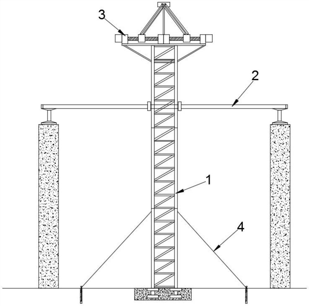
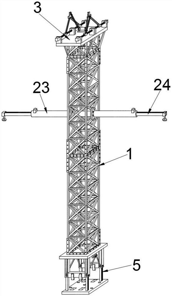
[0042] Embodiment 1: with reference to attached Figure 1-15 A main arch support device for the hoisting of a large-span steel structure roof is shown, including a steel arch support frame 1 and a horizontal auxiliary frame 2;

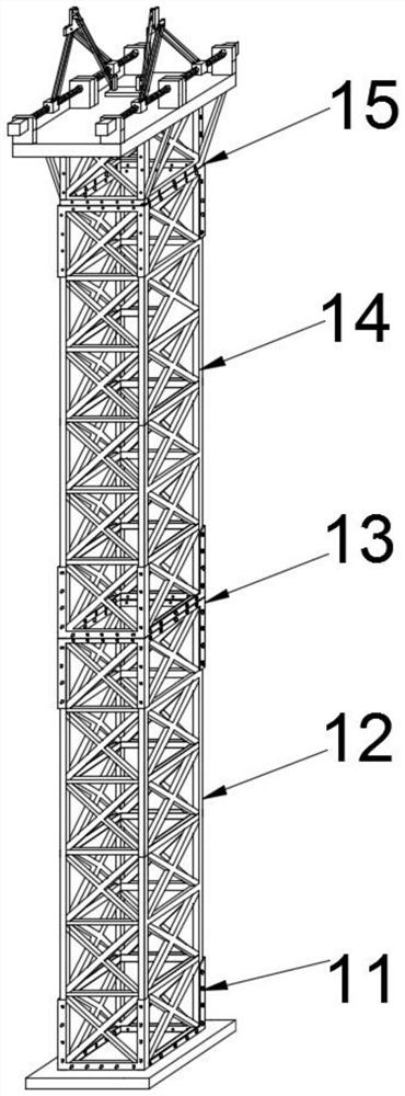
[0043] The steel arch support frame 1 is vertically installed between the two side walls, including a base 11, a bottom support 12, several standard supports 14 and a top support 15, and the lower end of the base 11 is provided with a The mobile mechanism 5, and in order to fix the device, the mobile mechanism 5 is installed on the bottom load-bearing support between the two side walls through the connecting bolt, the bottom support 12 is installed on the upper side of the base 11, and the bottom support 12. The standard support 14 and the top support 15 are connected by the support connector 13 and bolts to form a steel arch support frame for supporting the steel arch beam, and after installation, the position of the steel arch beam is adjusted. Fine...

Embodiment 2

[0055] Embodiment 2: Different from Embodiment 1, in order to facilitate the installation of the steel arch, the device is used to fine-tune the steel arch to facilitate installation and docking. The support mechanism 3 includes four degrees of freedom An adjustment unit and a load unit, the four-degree-of-freedom adjustment unit is symmetrically arranged, and the load-bearing unit is arranged between two symmetrically arranged four-degree-of-freedom adjustment units to carry the load on the steel arch; the load unit includes a transfer connector 33, a first The connecting rod 34 and the load plate 35, the transfer connector 33 is a T-shaped connector arranged above the support platform 152, and first hinge supports 334 are respectively arranged on the inner and outer sides of the transfer connector 33 And the hinge rod 331, the hinge rod 331 is used in conjunction with the four-degree-of-freedom adjustment unit, the first hinge support 334 is hingedly connected to one end of t...

Embodiment 3

[0059] Embodiment 3: Different from Embodiment 1, in order to facilitate the movement of the device during use, that is, after one span is hoisted, the device can be moved to install the next span, saving disassembly and installation process to improve work efficiency, the moving mechanism 5 includes an installation connecting plate 51, a first vertical rod 52, a second vertical rod 53, a roller 55 and an adjustment assembly, and the second vertical rod 53 is arranged under the bottom steel plate 111 side, and two adjacent second poles 53 are provided with connecting crossarms 54, the rollers 55 are installed on the connecting crossarms 54, and an adjustment groove 531 is provided on the second poles 53, so The adjustment groove 531 is used in conjunction with the movable end of one end of the first vertical rod 52, and the other fixed end of the first vertical rod 52 is arranged on the installation connecting plate 51, and a bolt connection is provided on the installation conn...


PUM


Abstract

The invention discloses a main arch supporting device for hoisting a large-span steel structure roof. The main arch supporting device comprises a steel arch supporting frame and a horizontal auxiliary frame, the steel arch supporting frame is vertically installed between the two side walls and comprises a base, a bottom supporting piece, a plurality of standard supporting pieces and a top supporting piece, a moving mechanism is arranged at the lower end of the base, and a supporting mechanism is arranged at the top of the top supporting piece; the horizontal auxiliary frame is horizontally installed on the steel arch supporting frame and comprises a limiting connecting piece, a flange connecting column and a horizontal supporting rod. According to the device, by arranging the supporting mechanism and the moving mechanism, the position of a hoisted steel arch can be adjusted, so that the steel arch is in tight and rapid butt joint and installation with an installation base of a corresponding span, and the installation efficiency and the installation precision are effectively improved; meanwhile, through the arrangement of the moving mechanism, fixing and moving can be combined, the position of the device is adjusted, and the device has the advantages of being convenient to use and move and capable of effectively improving the steel arch mounting efficiency and mounting precision.

Description

technical field [0001] The invention relates to the technical field of construction engineering design and construction, in particular to a main arch support device used for hoisting a large-span steel structure roof. Background technique [0002] With the rapid development and widespread application of steel structure workshops, the steel-frame combination form has been widely promoted. This type of workshop not only has the strength of concrete structures, but also has the advantages of fast construction progress and low cost by adopting steel structure forms in the outer enclosure structure; However, after the completion of the main structure construction, it caused difficulties in the construction of the large-span steel structure roof; in order to ensure the organic combination of the two and improve the installation quality, adapt to the development of this type of building form; ensuring the installation quality of the steel structure is an urgent problem that we need ...

Claims


Application Information

Patent Timeline
Patent Type & Authority Applications(China)
IPC IPC(8): E04G21/16E04G21/18
CPCE04G21/162E04G21/18Y02A40/25
Inventor 张文博贾志武段浩孙海刚王峰籍旭辉田园马超
Owner SHAANXI CONSTR ENG GRP CO LTD THE FIRST BUILDING
Learn More