Integrally-formed strip nail

A one-piece, nailing technology, applied in the direction of nails, U-shaped nails, connecting components, etc., can solve the problems of difficult processing, unevenness, high cost, etc., and achieve the effect of good clamping effect and straight structure

Pending Publication Date: 2022-05-06
APEX MFG
View PDF0 Cites 0 Cited by
  • Summary
  • Abstract
  • Description
  • Claims
  • Application Information

AI Technical Summary

Problems solved by technology

However, it is known that there is no more effective connection structure between adjacent U-shaped nails in the row of nails, resulting in that the arrangement of the U-shaped nails is easy to be relatively misaligned and not straight, and the known row of nails has a guide that matches the nail box. lead structure, and then the nailing effect is not good, and it is even easy to get stuck and damage the cable
[0004] One of the known cable fixing methods is achieved by passing a U-shaped metal nail through a plastic part with a pressure groove. The components are not integrally formed, which is difficult to process and expensive, and the metal nail is easy to cause damage to the cable. Loss, leakage, short circuit and other problems

Method used


Image

  • Integrally-formed strip nail
  • Integrally-formed strip nail
  • Integrally-formed strip nail

Examples


Embodiment Construction

[0027] The following examples illustrate the possible implementation forms of the present invention, but are not intended to limit the scope of protection of the present invention.

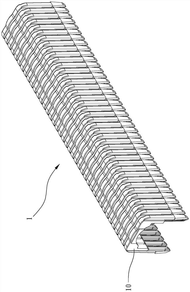
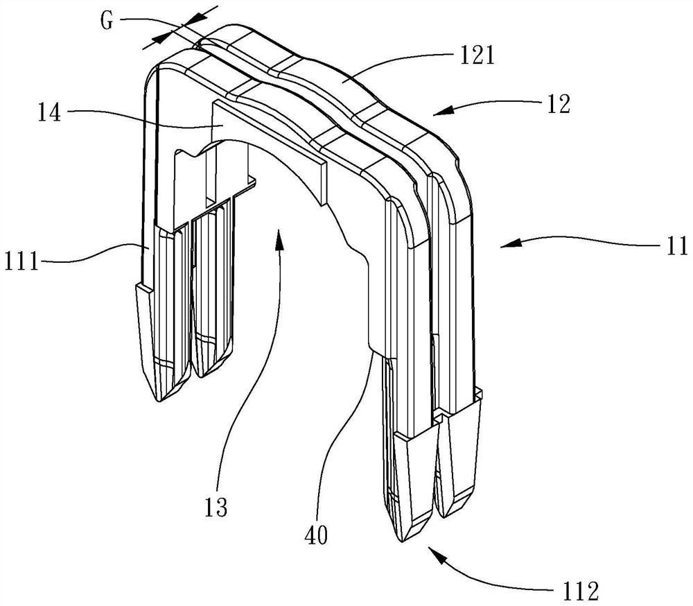
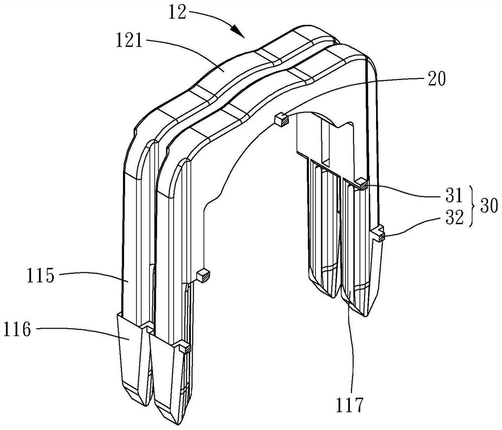
[0028] Please refer to Figures 1 to 7 , which shows a preferred embodiment of the present invention, the integrally formed nail row 1 of the present invention includes a plurality of nail needles 10 , a connecting portion and a stop portion 40 . The integrally formed nail row 1 is, for example, made of plastic, and can also be made of other materials.

[0029] Each of the nails 10 includes two legs 11 and a crown 12 connecting the two legs 11; the connecting portion is connected between two adjacent nails 10; the stopper 40 is on each of the legs of the nails 10 The portion 11 protrudes laterally and defines a receiving space 13 for receiving a cable with the crown portion 12 ; wherein, each of the leg portions 11 includes a spike 111 extending from the stop portion 40 . Thereby, it can ensure ...


PUM


Abstract

The invention relates to an integrally formed row nail, which comprises a plurality of nail needles, and each nail needle comprises two leg parts and a crown part connected with the two leg parts; the connecting part is connected between two adjacent nail needles; the stopping part laterally protrudes from the leg part of each nail needle, and an accommodating space for accommodating a cable is defined between the stopping part and the crown part; and each leg part comprises a nail foot extending from the stopping part.

Description

technical field [0001] The invention relates to an integrally formed nail row. Background technique [0002] In many fields, there is often a need to arrange cables according to different environments or work requirements, and the cables may be electrical cables or non-electric cables. Among them, the requirement of arranging conductive cables for building circuits is the most common. [0003] Wherein, the cable is usually fixed on a foundation (such as wood or similar foundation), because the cable is generally long and flexible, it is difficult to make it straight and positioned, so commonly used nail guns use such as U-shaped nails to fix . However, it is known that there is no more effective connection structure between adjacent U-shaped nails in the row of nails, resulting in that the arrangement of the U-shaped nails is easy to be relatively misaligned and not straight, and the known row of nails has a guide that matches the nail box. The lead structure, and then th...

Claims


Application Information

Patent Timeline
Patent Type & Authority Applications(China)
IPC IPC(8): F16B15/08
CPCF16B15/08
Inventor 胡志玮王景立
Owner APEX MFG
Why Eureka
Try Eureka