Deburring machine tool for numerical control vertical multi-axis linkage die casting machining

A multi-axis linkage, CNC vertical technology, applied in the direction of metal processing machinery parts, metal processing equipment, manufacturing tools, etc., can solve the problems of damage to the burr-free surface of the workpiece, manual grinding time-consuming and laborious, and cumbersome processes, etc.

Active Publication Date: 2022-05-10
哈工大机器人(中山)无人装备与人工智能研究院
View PDF8 Cites 2 Cited by
  • Summary
  • Abstract
  • Description
  • Claims
  • Application Information

AI Technical Summary

Problems solved by technology

[0003] In the prior art, there are industrial methods such as shot blasting and chemical treatment for the burrs on the surface of workpieces, as well as small-batch methods such as manual grinding, and some technicians use machining methods to remove burrs. These methods have certain limitations. Automated physical methods such as shot blasting are not suitable for soft aluminum parts, chemical treatment is cumbersome, and manual grinding is time-consuming and laborious. However, when CNC machine tools are used for machining to remove burrs, sometimes there will be excessive contact force between the deburring knife and the workpiece. Too large to damage the burr-free surface on the workpiece, or the contact force is too small to effectively remove the burr, and the contact force between the tool and the workpiece cannot be found to obtain a balance point

Method used


Image

  • Deburring machine tool for numerical control vertical multi-axis linkage die casting machining
  • Deburring machine tool for numerical control vertical multi-axis linkage die casting machining
  • Deburring machine tool for numerical control vertical multi-axis linkage die casting machining

Examples


Embodiment Construction

[0029] The following will clearly and completely describe the technical solutions in the embodiments of the present invention with reference to the accompanying drawings in the embodiments of the present invention. Obviously, the described embodiments are only some, not all, embodiments of the present invention. Based on the embodiments of the present invention, all other embodiments obtained by persons of ordinary skill in the art without making creative efforts belong to the protection scope of the present invention.

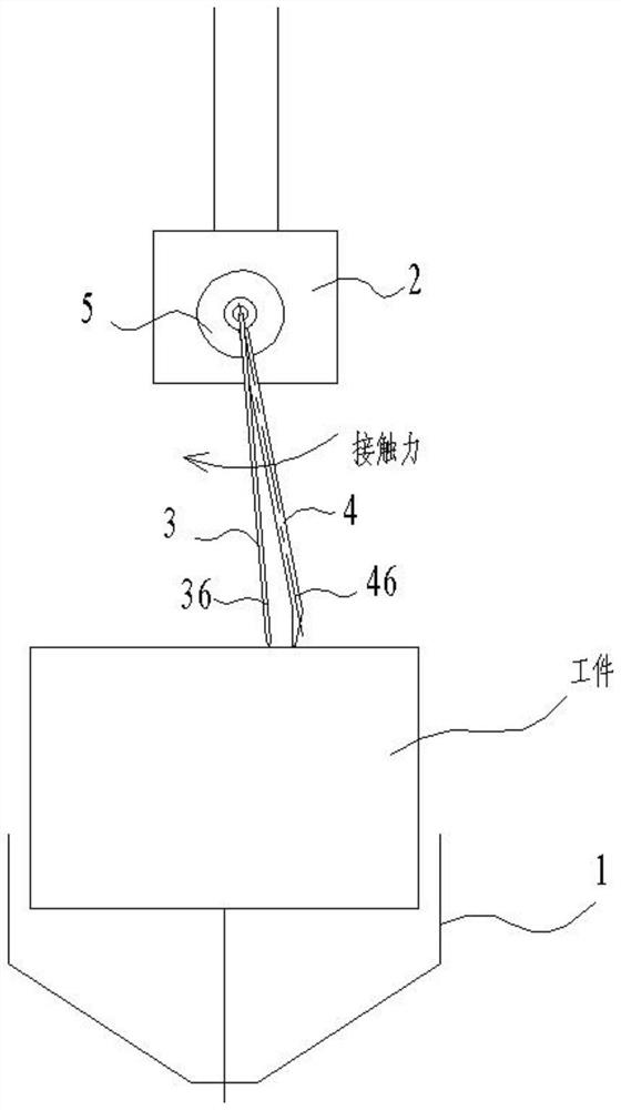
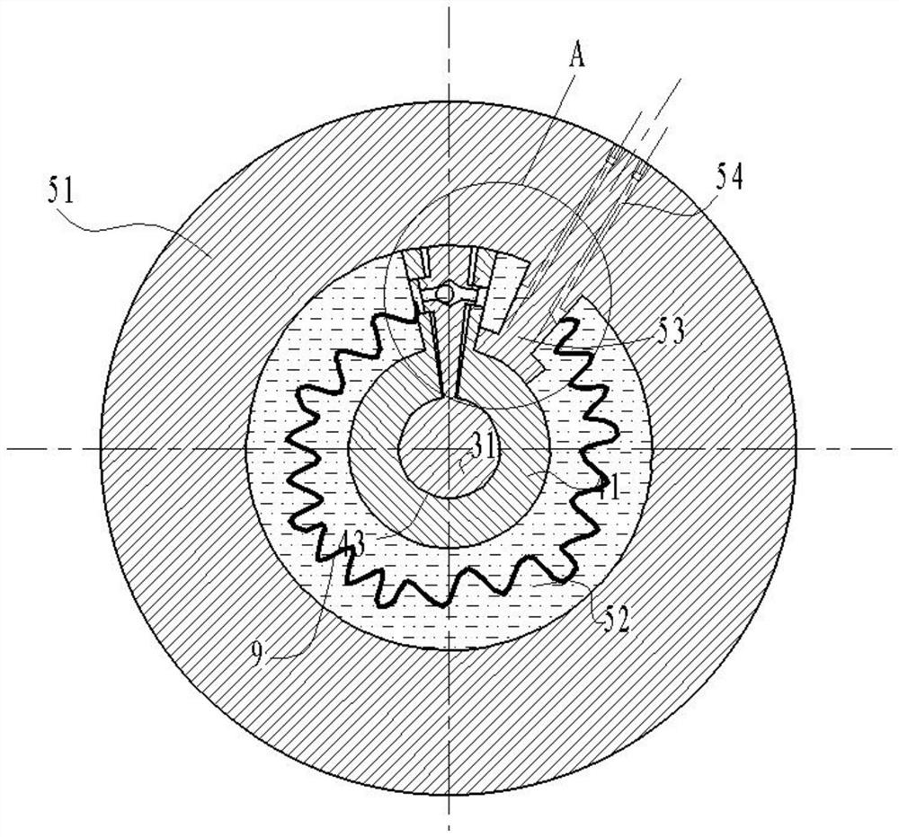
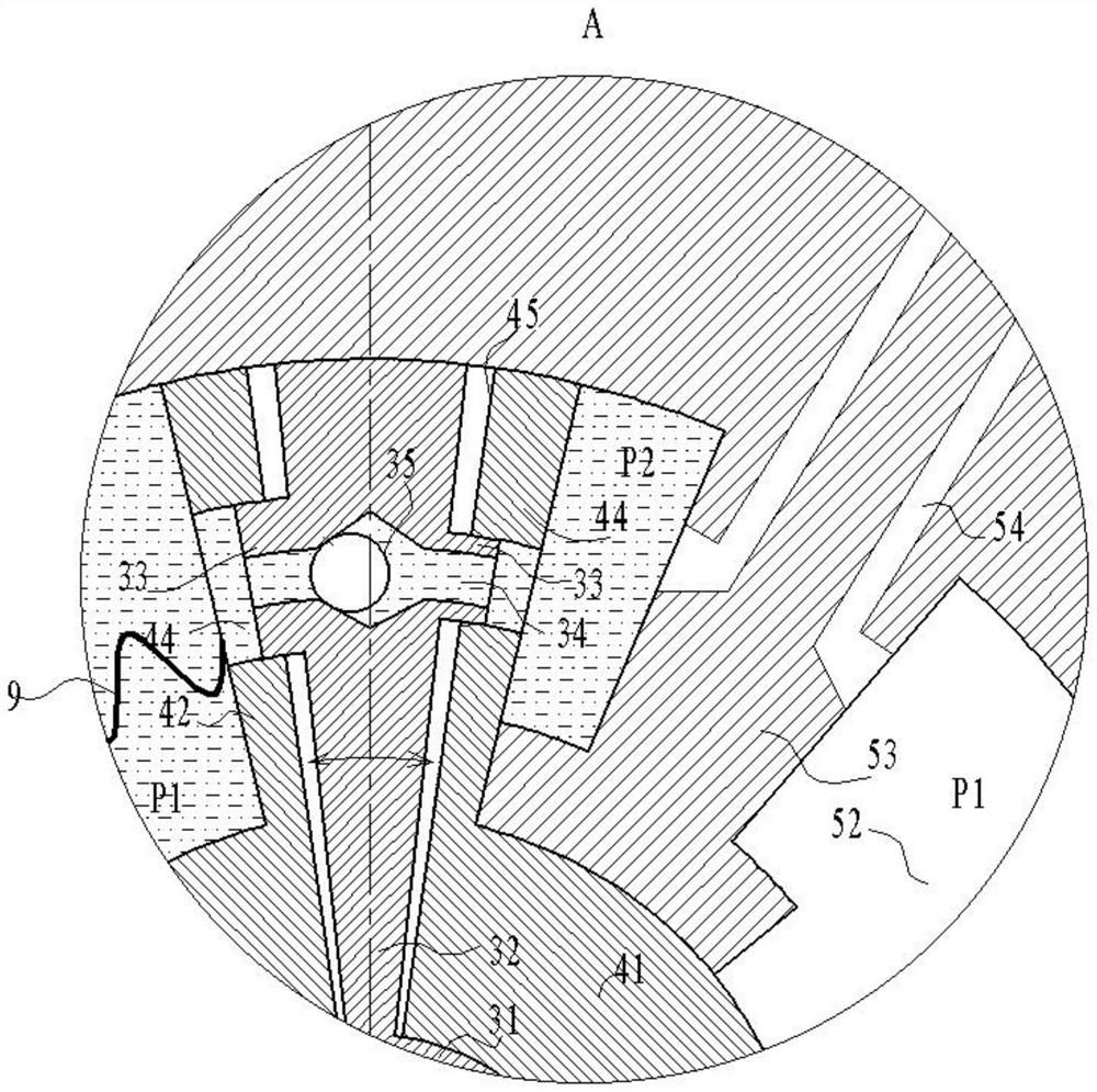
[0030] see Figure 1-Figure 6 , the present invention provides technical solutions:

[0031]A deburring machine tool for CNC vertical multi-axis linkage die-casting processing, including a chucking head 1 and a tool holder 2, the chucking head 1 clamps a workpiece, and a deburring knife is installed on the tool holder 2 and drives the deburring knife along the workpiece The surface moves, and the deburring machine tool also includes a floating core 4 and a ba...


PUM


Abstract

The invention discloses a numerical control vertical type multi-axis linkage deburring machine tool for die casting machining, which comprises a clamping head, a tool apron, a deburring tool, a floating core and a base cylinder, the clamping head clamps a workpiece, the tool apron is provided with a deburring tool and drives the deburring tool to move along the surface of the workpiece, the deburring machine tool further comprises a floating core and a base cylinder, and the base cylinder is fixedly arranged on the tool apron. The floating core is rotationally installed on the base cylinder, the deburring cutter is installed at the end, away from the base cylinder, of the floating core, the base cylinder applies steering force to the floating core so that the end, provided with the deburring cutter, of the floating core can be tightly attached to a workpiece, and the steering force applied by the base cylinder to the floating core is increased when vibration occurs in the deburring process. A workpiece is clamped and fixed by the clamping head, the deburring cutter is driven by the floating core to perform feeding motion to scrape burrs on the surface or burrs on the edges from the surface of the workpiece, the floating core and the base cylinder serve as middle structures for connecting the deburring cutter and the cutter holder, the deburring cutter is installed in a floating mode, the contact force between the deburring cutter and the workpiece is a variable value, and the deburring cutter can be driven by the floating core to perform feeding motion to scrape burrs on the surface or burrs on the edges. The purpose of floating adjustment is achieved.

Description

technical field [0001] The invention relates to the technical field of deburring equipment, in particular to a numerically controlled vertical multi-axis linkage deburring machine tool for processing die castings. Background technique [0002] The surface of die-casting blanks and semi-finished parts often has a large number of burrs. If this surface does not need further processing, the burrs will affect the appearance of the workpiece. If this surface needs to be finished later, the burrs on the surface of the die-casting will affect the subsequent The processing, positioning and other processes of the process, so the burrs on the surface of the parts generally need to be cleaned. [0003] In the prior art, there are industrial methods such as shot blasting and chemical treatment for the burrs on the surface of workpieces, as well as small-batch methods such as manual grinding, and some technicians use machining methods to remove burrs. These methods have certain limitatio...

Claims


Application Information

Patent Timeline
Patent Type & Authority Applications(China)
IPC IPC(8): B23D79/00B23Q3/00
CPCB23D79/00B23Q3/00
Inventor 章明褚巍
Owner 哈工大机器人(中山)无人装备与人工智能研究院
Why Eureka
Try Eureka