Main shaft capable of electromagnetically adjusting pre-tightening force of bearing

A technology for adjusting the bearing and preloading force, which is applied to the parts of grinding machine tools, metal processing equipment, manufacturing tools, etc. Stable operation, reduced noise and low cost

Active Publication Date: 2022-05-10
广东创能精密机械有限公司
View PDF16 Cites 3 Cited by
  • Summary
  • Abstract
  • Description
  • Claims
  • Application Information

AI Technical Summary

Problems solved by technology

[0005]In order to overcome the need for a tighter connection between the bearing and the inner shaft of the existing main shaft, and it is difficult for workers to grasp during disassembly and maintenance, and it is easy to be damaged if the operation is not standardized The shortcomings of the inner shaft, and the need to solve the problem that the existing bearings and the inner shaft need to be more tightly connected, the technical problem to be solved is: provide a main shaft that can be disassembled easily and electromagnetically adjusts the preload of the bearing

Method used


Image

  • Main shaft capable of electromagnetically adjusting pre-tightening force of bearing
  • Main shaft capable of electromagnetically adjusting pre-tightening force of bearing
  • Main shaft capable of electromagnetically adjusting pre-tightening force of bearing

Examples


Embodiment 1

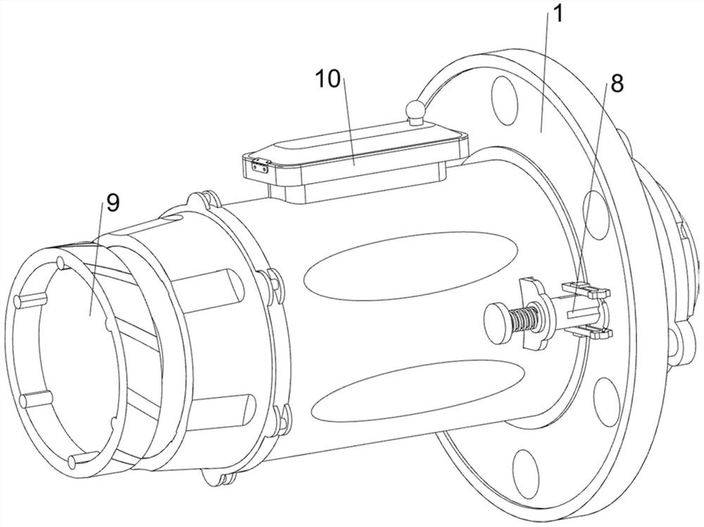
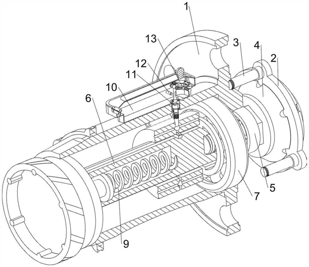
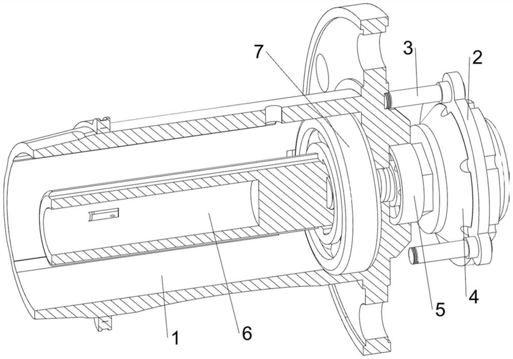
[0035] A main shaft for electromagnetically adjusting bearing pretightening force, in Figure 1-3As shown in , it includes an outer shaft 1, a first connecting block 2, a bolt 3, a servo motor 4, a threaded shaft 5, an inner shaft 6, a bearing 7, a pre-tightening mechanism 8 and a replacement mechanism 9, and the right side of the outer shaft 1 is threaded The way of connection is connected with three bolts 3 for fixing at even intervals, and the first connecting block 2 is slidingly connected between the right sides of the three bolts 3, and the servo motor 4 is installed on the first connecting block 2, and the servo motor 4 outputs A threaded shaft 5 is clamped on the shaft, and the threaded shaft 5 is slidingly connected with the right side of the outer shaft 1. The inner right side of the outer shaft 1 is slidingly connected with a bearing 7, and the inner ring of the bearing 7 is clamped with a shaft for driving the workpiece to rotate. The inner shaft 6, the right side ...

Embodiment 2

[0040] On the basis of Example 1, in figure 1 , figure 2 , Figure 7 with Figure 8 Shown in, also includes lubricating mechanism 10, and lubricating mechanism 10 includes material discharging frame 100, protective cover 101, hinge 102, annular shaft 103, rotating block 104, unloading pipe 105, lifting pipe 106, connecting pipe 107 and Return spring 108, the top right side of the outer shaft 1 is provided with a discharge frame 100 for storing lubricating oil, the left side of the discharge frame 100 is connected with a dustproof protective cover 101 through a hinge 102, the hinge 102 can rotate automatically, and the protective cover 101 is a transparent material, which is convenient to check the remaining amount of lubricating oil inside the discharge frame 100. The protective cover 101 is in contact with the top of the discharge frame 100. The inner right side of the outer shaft 1 is slidingly provided with an annular shaft 103. The inside of the annular shaft 103 is ope...


PUM


Abstract

The invention relates to a main shaft, in particular to a main shaft capable of electromagnetically adjusting bearing pre-tightening force. The invention provides the main shaft capable of electromagnetically adjusting the pre-tightening force of the bearing, which is convenient to disassemble. A main shaft capable of electromagnetically adjusting bearing pre-tightening force comprises an outer shaft, a first connecting block, bolts, a servo motor, a threaded shaft and the like, the three bolts are evenly connected to the right side of the outer shaft in a threaded connection mode, the first connecting block is slidably connected between the right sides of the three bolts, and the servo motor used for driving is arranged on the first connecting block. And a threaded shaft is clamped on an output shaft of the servo motor. The electric push rod is started, the clamping block can rotate to not clamp the millstone any more, the millstone can be taken out to be replaced, a proper millstone can be selected according to the type of a machined object, and therefore disassembly is convenient, and meanwhile maintenance is convenient.

Description

technical field [0001] The invention relates to a main shaft, in particular to a main shaft for electromagnetically adjusting the pretightening force of a bearing. Background technique [0002] The spindle of a CNC machine tool refers to the axis on the machine tool that drives the workpiece or tool to rotate. It is usually composed of a spindle, bearings, and transmission parts (gears or pulleys). It is mainly used to support the transmission parts in the machine. In order to improve the bearing rigidity of the electric spindle, suppress the vibration and the sliding of the ball revolution and rotation during high-speed rotation, and improve the rotation accuracy of the shaft, the rolling bearings used on the electric spindle need to be preloaded. [0003] The existing main shaft generally includes an outer shaft, a first connecting block, a bolt, a servo motor, a threaded shaft, an inner shaft and a bearing, and the right side of the outer shaft is evenly connected with th...

Claims


Application Information

Patent Timeline
Patent Type & Authority Applications(China)
IPC IPC(8): B24B41/04B24B55/00
CPCB24B41/04B24B55/00
Inventor 龚创宁崔亚雄
Owner 广东创能精密机械有限公司
Why Eureka
Try Eureka