Rolling device for road construction

A rolling device and road construction technology, applied in the field of rolling devices, can solve the problems of unsatisfactory rolling effect and easy residual small potholes on the road surface, and achieve the effect of good flattening effect, sufficient rolling, and flexible adjustment.

Pending Publication Date: 2022-05-10
苏亮
View PDF9 Cites 0 Cited by
  • Summary
  • Abstract
  • Description
  • Claims
  • Application Information

AI Technical Summary

Problems solved by technology

[0005] In order to overcome the disadvantages that the existing flattening device only relies on one roller to roll the road, the effect is not ideal, and small potholes are easy to remain on the road surface, the technical problem of the present invention is to provide a road that can use different rolling methods to Rolling device for road construction to achieve better rolling effect

Method used


Image

  • Rolling device for road construction
  • Rolling device for road construction
  • Rolling device for road construction

Examples


Embodiment 1

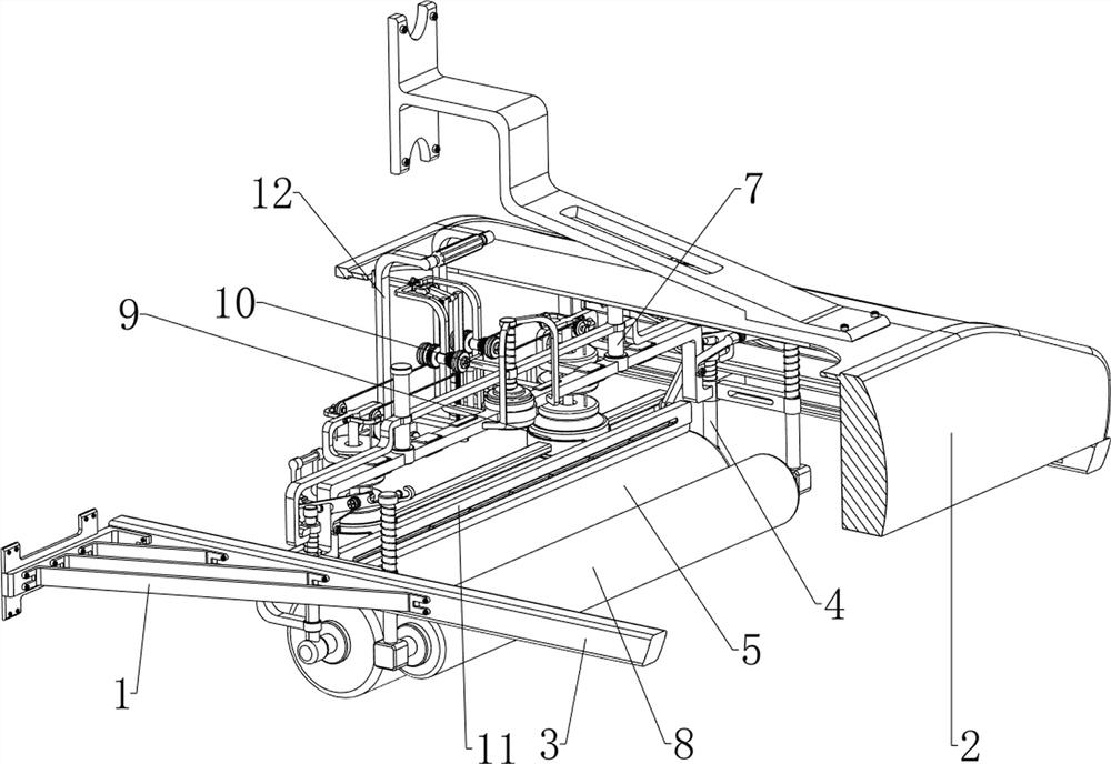
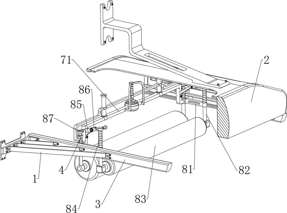
[0036] A rolling device for road construction, in Figure 1-3 As shown in , it includes a first bracket 1, a frame body 2, a rodless cylinder 3, a sliding rod 4, a first roller 5, a first spring 6, a lifting mechanism 7 and a flattening mechanism 8, and the bottom of the frame body 2 is symmetrical front and rear Rodless cylinder 3 is installed, and the first support 1 is all connected with the mode of bolt connection on the left side front and back side walls of two rodless cylinders 3, and the all sliding connection on the moving parts of two rodless cylinders 3 Sliding rods 4, between the lower sides of the two sliding rods 4, there is a first roller 5 that can flatten road potholes and bumps, and the upper side of the two sliding rods 4 and the rodless cylinder 3 on the same side The first spring 6 which acts as a buffer is connected between the tops of the moving parts, and the lifting mechanism 7 which is convenient for switching the rolling mode is connected between the...

Embodiment 2

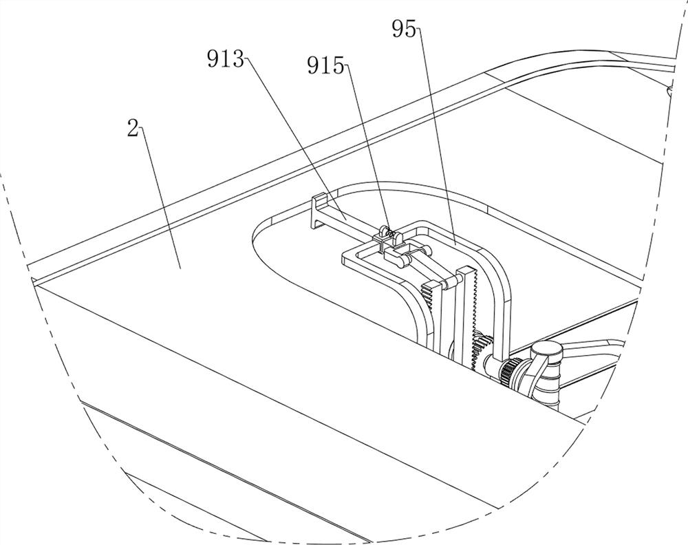
[0041] On the basis of Example 1, in image 3 , Figure 7 , Figure 8 with 9 As shown in the figure, it also includes a weighting mechanism 9, and the weighting mechanism 9 includes a material receiving frame 91, a third support 92, a fourth support 93, a first winding wheel 94, a fifth support 95, a second winding wheel 96, Stay cord 97, iron block 98, the third slide bar 99, the first rack 910, the third spring 911, the first gear 912, push block 913, the second fork 914 and the fourth spring 915, two slide bars 4 The lower part of the frame is connected with a receiving frame 91, and the front and rear sides of the connecting frame 71 are connected with a third bracket 92 by means of bolt connection, and the left and right sides of the two third brackets 92 are welded with a fourth bracket 93 for supporting , the four fourth brackets 93 are all rotatably provided with a first reel 94, the left side wall in the middle of the connecting frame 71 is provided with a fifth br...


PUM


Abstract

The invention relates to a rolling device, in particular to a rolling device for road construction. According to the rolling device for road construction, a good rolling effect can be achieved by adopting different rolling modes. A rolling device for road construction comprises first supports, a frame body, rodless air cylinders, sliding rods and the like, the rodless air cylinders are symmetrically arranged at the bottom of the frame body front and back, the first supports are arranged on the front side wall and the rear side wall of the left side of each rodless air cylinder, and the sliding rods are connected to moving parts of the two rodless air cylinders in a sliding mode. The rodless air cylinder works to enable the first roller to move left and right repeatedly to roll large pits and protrusions in a road, in the later period, the height of the first roller and the height of the second roller can be converted through the lifting mechanism, small pits left in the road can be rolled through the second roller, and the good flattening effect can be achieved through the rolling mode.

Description

technical field [0001] The invention relates to a rolling device, in particular to a rolling device used for road construction. Background technique [0002] The road is an infrastructure for all kinds of trackless vehicles and pedestrians. When constructing the road, it is necessary to flatten the potholes and protrusions in the road to facilitate the passage of vehicles, and then use the rolling device to achieve better construction effect. [0003] Publication No. CN213328572U is a road flattening device for building construction, which solves the problem that the flattening device does not have the function of crushing hard rocks. There is a slot, and a screw rod is installed between the inner walls on both sides of the top of the slot. One end of the screw rod is provided with a first motor, and the screw rod is provided with a mounting block, which is threadedly connected with the screw rod; the bottom of the mounting block An electric push rod is installed at the en...

Claims


Application Information

Patent Timeline
IPC IPC(8): E01C19/23E01C23/06E01C23/088
CPCE01C19/23E01C19/236E01C19/238E01C23/06E01C23/088Y02A30/60
Inventor 苏亮
Owner 苏亮
Why Eureka
Try Eureka