Hydraulically-driven traffic lifting column

A lifting column and traffic technology, applied in traffic signals, traffic restrictions, roads and other directions, can solve problems such as motor damage and failure to work normally, and achieve the effect of prolonging the service life and improving traffic safety

Pending Publication Date: 2022-05-10
WUXI AOYUTE NEW TECH DEV
View PDF0 Cites 0 Cited by
  • Summary
  • Abstract
  • Description
  • Claims
  • Application Information

AI Technical Summary

Problems solved by technology

[0003] The purpose of the present invention is to provide a hydraulically driven traffic lifting bollard, which has the advantages of hydraulic cylinder drive, and solves the problem that the existing traffic lifting bollards are all driven by motors, and cannot work normally when the power is cut off or the motor is damaged.

Method used


Image

  • Hydraulically-driven traffic lifting column
  • Hydraulically-driven traffic lifting column
  • Hydraulically-driven traffic lifting column

Examples


Embodiment Construction

[0015] The following will clearly and completely describe the technical solutions in the embodiments of the present invention with reference to the accompanying drawings in the embodiments of the present invention. Obviously, the described embodiments are only some, not all, embodiments of the present invention. Based on the embodiments of the present invention, all other embodiments obtained by persons of ordinary skill in the art without making creative efforts belong to the protection scope of the present invention.

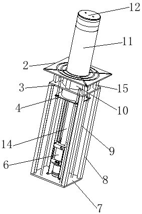
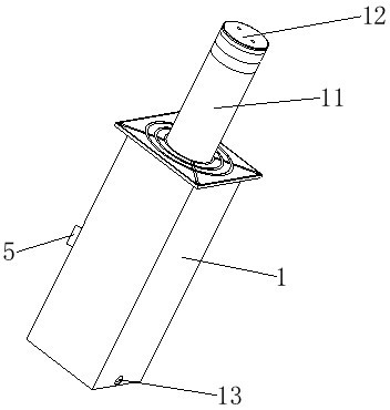
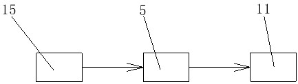
[0016] see figure 1 , figure 2 and image 3 , a hydraulically driven traffic lifting column, comprising a support plate 1, a bottom plate 7 is fixedly connected around the bottom of the support plate 1, a hydraulic cylinder 6 is fixedly connected to the middle end of the top of the bottom plate 7, and a hydraulic cylinder 6 is fixedly connected to the top end of the hydraulic cylinder 6. The rod 14 can make the lifting column have the ability to be driven b...


PUM


Abstract

The hydraulically-driven traffic lifting column comprises a supporting plate, bottom plates are fixedly connected to the periphery of the bottom of the supporting plate, a hydraulic cylinder is fixedly connected to the middle end of the top of each bottom plate, a hydraulic rod is fixedly connected to the top end of each hydraulic cylinder, and a column body is fixedly connected to the top end of each hydraulic rod; an LED lamp strip is fixedly connected to the outer surface of the column body, a flange is fixedly connected to the top end of the supporting plate, the inner surface of the flange is movably connected with the column body, guide rods are fixedly connected to the periphery of the top of the supporting plate, and a positioning plate is slidably connected to the upper ends of the outer surfaces of the guide rods. According to the traffic lifting column, the hydraulic cylinder is fixedly connected to the middle end of the top of the bottom plate, and the hydraulic rod is fixedly connected to the top end of the hydraulic cylinder, so that the lifting column can be driven by the hydraulic cylinder, and the problem that an existing traffic lifting column is driven by a motor to ascend and descend and cannot work normally during power failure or motor damage is solved.

Description

technical field [0001] The invention relates to the technical field of traffic control equipment for passageways, in particular to a hydraulically driven traffic lifting column. Background technique [0002] With the rapid development of my country's national economy and the rapid development of urban traffic, access control equipment used in emergency situations has become an indispensable part of our lives, and traffic lifting bollards are one of the access control equipment. The traffic lifting bollard is a device that controls and prevents vehicles from forcibly passing through the customs among public security products and equipment. It can be used in conjunction with a computer control system, or it can be used alone. But its lifting of existing traffic lifting column is all driven by motor, and it can't work normally when power failure or motor damage. Contents of the invention [0003] The purpose of the present invention is to provide a hydraulically driven traff...

Claims


Application Information

Patent Timeline
Patent Type & Authority Applications(China)
IPC IPC(8): E01F13/04E01F9/615E01F9/688
CPCE01F13/046E01F9/617E01F9/688
Inventor 张鹏
Owner WUXI AOYUTE NEW TECH DEV
Why Eureka
Try Eureka