Projection welding nut with annularly distributed welding legs

A technology of projection welding nuts and welding legs, applied in nuts, welding equipment, threaded fasteners, etc., can solve the problems of high cost, long time, low efficiency, etc., and achieve the effect of solving high cost and improving bonding force and strength.

Pending Publication Date: 2022-05-10
南昌江铃集团联成汽车零部件有限公司
View PDF0 Cites 0 Cited by
  • Summary
  • Abstract
  • Description
  • Claims
  • Application Information

AI Technical Summary

Problems solved by technology

[0005] However, welding on plates with a thickness of more than 3mm using the se

Method used


Image

  • Projection welding nut with annularly distributed welding legs
  • Projection welding nut with annularly distributed welding legs
  • Projection welding nut with annularly distributed welding legs

Examples


Embodiment 1

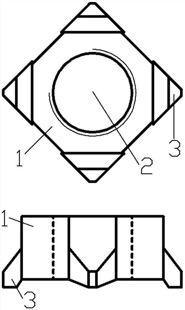
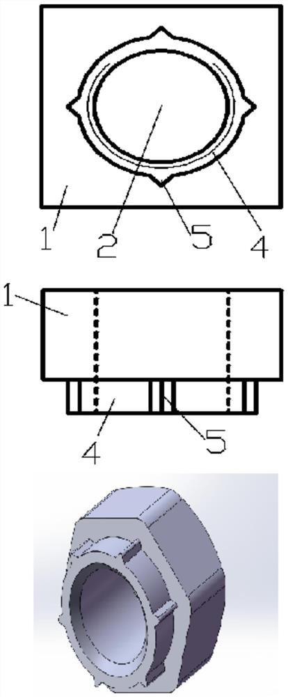
[0028] A projection welding nut with circular distribution of welding feet, such as figure 2 As shown, it includes a head plate 1 and a columnar portion 4. The middle part of the head plate 1 and the columnar portion 4 forms a through portion 2; the columnar portion 4 is provided with four circularly distributed longitudinal welding feet 5 that are separated from each other.

Embodiment 2

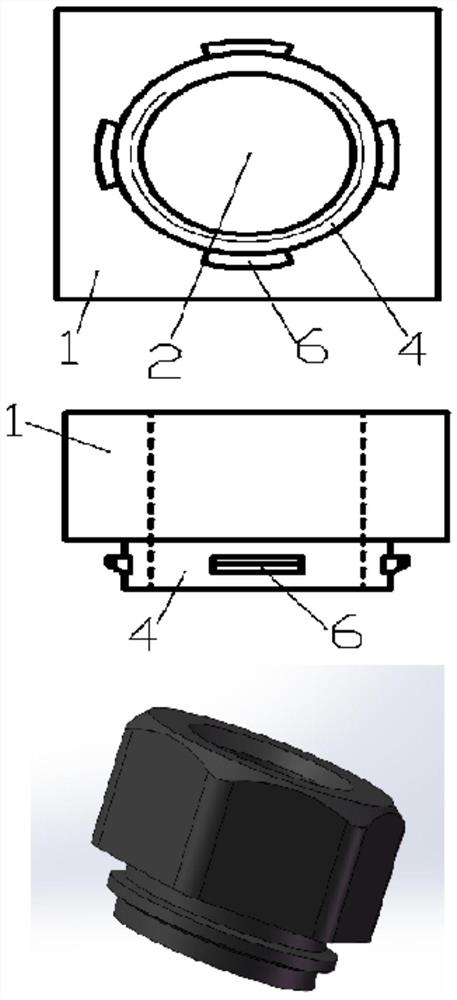
[0030] A projection welding nut with circular distribution of welding feet, such as image 3 As shown, it includes a head plate 1 and a columnar portion 4. The middle part of the head plate 1 and the columnar portion 4 forms a through portion 2; the columnar portion 4 is provided with four circularly distributed transverse welding feet 6 that are separated from each other.

Embodiment 3

[0032] A projection welding nut with circular distribution of welding feet, on which the base surface of the longitudinal welding feet 5 is gradually enlarged, as shown in Figure 4 As shown, the farther the distance from the head plate 1 is, the larger the base surface of the longitudinal welding leg 5 is, and the rest are the same as in the first embodiment.


PUM


Abstract

The invention discloses a projection welding nut with annularly distributed welding legs, which can effectively adapt to a plate with the thickness of more than 3mm through a columnar part and annularly distributed welding legs arranged on the columnar part in cooperation with a projection welding process, and can greatly improve the bonding force and strength of the projection welding nut and the plate while improving the strength of the plate.

Description

technical field [0001] The invention relates to a projection welding nut, in particular to a projection welding nut with circularly distributed welding legs. Background technique [0002] With the gradual increase in the number of cars per capita in China, traffic accidents have also increased. Consumers have higher and higher requirements for the strength of car bodies, and the thickness of plates for car safety energy-absorbing parts is also gradually increasing. [0003] Traditional thin sheets generally use traditional projection welding nuts (such as figure 1 As shown) and projection welding process for welding, since the plate is thinner, the penetration depth and heat-affected zone after welding are larger, and the bonding force and strength between the projection welding nut and the plate after welding are guaranteed. [0004] However, as the thickness of the plate increases, the penetration depth and heat-affected zone after welding are greatly affected, and the bo...

Claims


Application Information

Patent Timeline
IPC IPC(8): F16B37/06B23K11/14
CPCF16B37/061B23K11/14
Inventor 刘峰刘慧东范强强胡发亮谭国辉
Owner 南昌江铃集团联成汽车零部件有限公司
Why Eureka
Try Eureka