Gravity locking valve for dust collection of boiler

A technology of gravity lock and boiler, applied in the field of air lock valve, can solve the problems of lax closing, deformation of valve head connecting rod, air leakage valve head, etc., and achieve the effect of environmental protection and energy saving

Active Publication Date: 2022-05-10
ANHUI NARADA RENEWABLE RESOURCE TECH CO LTD
View PDF9 Cites 0 Cited by
  • Summary
  • Abstract
  • Description
  • Claims
  • Application Information

AI Technical Summary

Problems solved by technology

Due to the error of the moving distance of the push rod and the deformation of the connecting rod of the valve head, air leakage and wear of the valve head are often caused by lax closing.
In addition, large pieces of foreign matter are often stuck in the flap valve, which will also cause damage to the connecting rod structure, and even cause the motor to burn out or the reducer to fail and deform.

Method used


Image

  • Gravity locking valve for dust collection of boiler
  • Gravity locking valve for dust collection of boiler
  • Gravity locking valve for dust collection of boiler

Examples


Embodiment 1

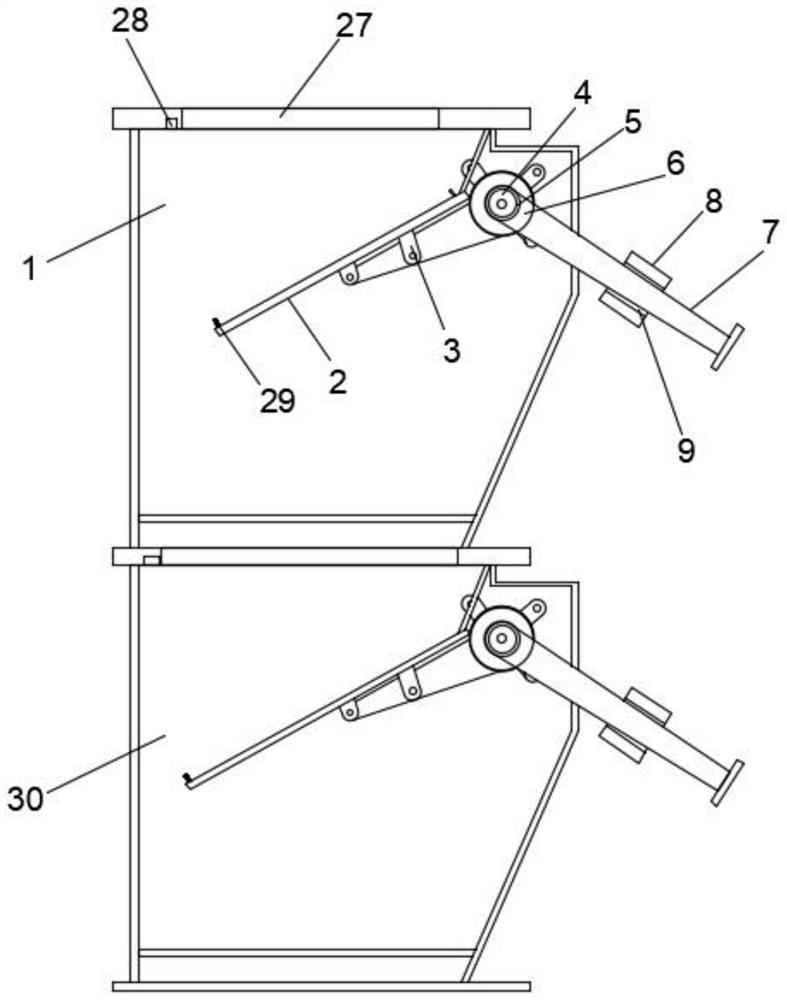
[0029] Such as Figure 1-3 As shown, a gravity air lock valve for boiler dust collection proposed by the present invention includes a first valve body 1, and the inside of the first valve body 1 is fixedly connected with a rotating shaft 4 near the left side, through which the rotating shaft 4 can effectively The bearing 6 and the weight frame 7 are rotated and limited. The outer surface of the rotating shaft 4 is provided with a bearing 6, and the bearing 6 is sleeved on the outer surface of the rotating shaft 4. The outer surface of the rotating shaft 4 is fixedly connected near the front end. There is a weight frame 7, and the weight frame 7 can effectively limit the sliding of the weight 8, and the weight frame 7 has a T-shaped structure, and the outer surface of the weight frame 7 of the T-shaped structure is covered with a weight 8 , using the gravity of the weight 8 to open and close the valve head 2, so that no external motor mechanical power is needed, and the purpose...

Embodiment 2

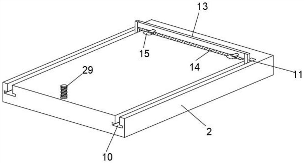
[0033] Such as Figure 1-6 As shown, the outer surface of the upper end of the push rod 3 is fixedly connected with the valve head 2, and the outer surface of the upper end of the valve head 2 is provided with a first chute 10 near both ends, and the first chute 10 is in a T-shaped structure. The inside of the chute 10 is slidably connected with a slider 11, and the slider 11 is also in a T-shaped structure. The first chute 10 of the T-shaped structure and the slider 11 of the T-shaped structure are matched and slid. The first chute 10 and the slider 11 can make the slider 11 effectively slide inside the first chute 10, and will not break away from the first chute 10 when sliding. The outer surface of the upper end of the slider 11 is fixedly connected with a connection rod 13, and the connecting rod 13 is connected with the sliders 11 inside the two first chute 10, the outer surface of the lower end of the connecting rod 13 is fixedly connected with a scraper 14, and the scra...

Embodiment 3

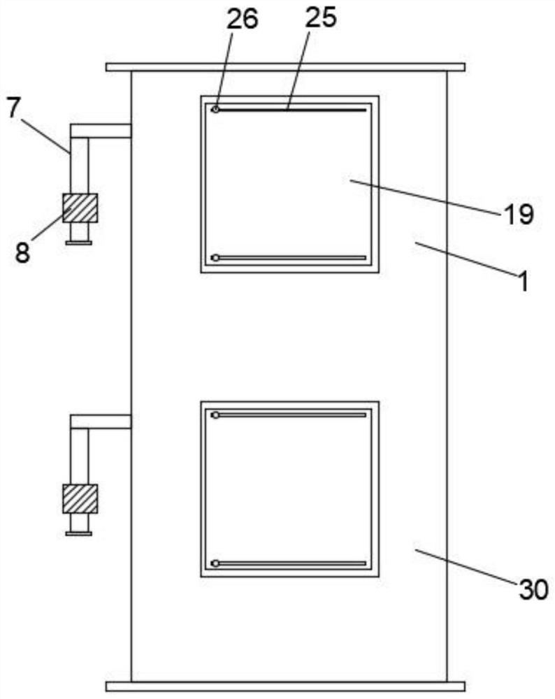
[0038] Such as Figure 2-8 As shown, the right outer surface of the first valve body 1 is provided with an inspection window 19 close to the middle position, the inspection window 19 is fixed to the outer surface of the first valve body 1 by hinges, and the inspection window 19 is opened from left to right, and the inspection window 19 A scraper 20 is provided on the outer surface of the left side, and the inner surface of the maintenance window 19 can be scraped and cleaned by using the scraper 20, which can make it easier to see from the outside to the inside, and is convenient for the staff to check. The right side of the scraper 20 The outer surface of the side is fixedly connected with an L-shaped rod 21 near the upper end and the lower end. The scraper 20 can be effectively driven to move by the L-shaped rod 21. The inside of the inspection window 19 is provided with a through groove 22 near the upper end. The left side of the inspection window 19 The side outer surface ...


PUM


Abstract

The gravity blocking valve comprises a first valve body, a rotating shaft is fixedly connected to the position, close to the left side, of the interior of the first valve body, dust is received through the upper end of a valve head, and after the received dust is too much, due to the fact that the weight of the dust is larger than that of a heavy hammer, the gravity blocking valve is closed. The valve head is pressed downwards, the heavy hammer slides towards one side on the heavy hammer frame, the valve head is opened and inclines towards the interior of the first valve body, dust falls into the first valve body, after falling, the valve head is reset through the gravity of the heavy hammer so that the dust can be conveniently used next time, and meanwhile the air locking effect can be effectively achieved; and then the dust falls into the outer surface of the valve head on the second valve body at the lower end, so that the device can achieve the purposes of environmental protection and energy conservation by virtue of gravity driving without using external motor mechanical power while having a better air locking effect; and dust attached to the outer surface of the valve head can be effectively scraped, and the later use effect of the device is improved.

Description

technical field [0001] The invention relates to the field of air lock valves, in particular to a gravity air lock valve for boiler dust collection. Background technique [0002] The air lock valve is used in the pneumatic conveying system. For the positive pressure conveying system or the negative pressure conveying system, the air lock valve can evenly and continuously supply the material to the conveying pipe, so as to ensure that the gas and solid in the pneumatic conveying pipe are relatively stable, so that the pneumatic conveying can It works normally, and at the same time, it can cut off the upper and lower parts of the air lock valve. It acts as a gas lock. [0003] Most of the existing air lock valves are driven by electric or pneumatic means, and adopt an actuator in which the push rod and the crank are connected by living hinges, and the closing and opening of the valve head are positioned by adjusting the length of the push rod. Due to the error of the moving d...

Claims


Application Information

Patent Timeline
Patent Type & Authority Applications(China)
IPC IPC(8): F16K1/22F16K1/36F16K1/32F16K27/02B08B1/00B08B13/00
CPCF16K1/22F16K1/36F16K1/32F16K27/0218B08B1/005B08B1/008B08B13/00
Inventor 史伟伟卢山龙宋宣都
Owner ANHUI NARADA RENEWABLE RESOURCE TECH CO LTD
Why Eureka
Try Eureka