Diamond roller finished product detection device

A diamond roller, finished product inspection technology, applied in measuring devices, workpiece clamping devices, instruments, etc., can solve the problems of general tightness, inability to quickly perform multi-point inspection, etc., to facilitate directional inspection, improve accuracy, The effect of improving detection efficiency

Pending Publication Date: 2022-05-10
孙晖
View PDF1 Cites 0 Cited by
  • Summary
  • Abstract
  • Description
  • Claims
  • Application Information

AI Technical Summary

Problems solved by technology

[0005] In order to overcome the shortcomings of the existing diamond roller finished product detection device that the diamond roller is insufficiently limited, the fastness is general, and multi-point detection cannot be performed quickly, the purpose of the present invention is to provide a diamond roller that can better limit the position of the diamond roller. And the diamond roller finished product detection device with high reliability of detection results

Method used


Image

  • Diamond roller finished product detection device
  • Diamond roller finished product detection device
  • Diamond roller finished product detection device

Examples


Embodiment 1

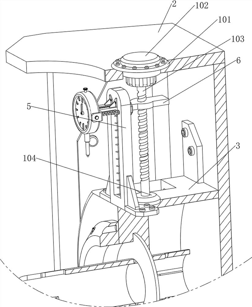
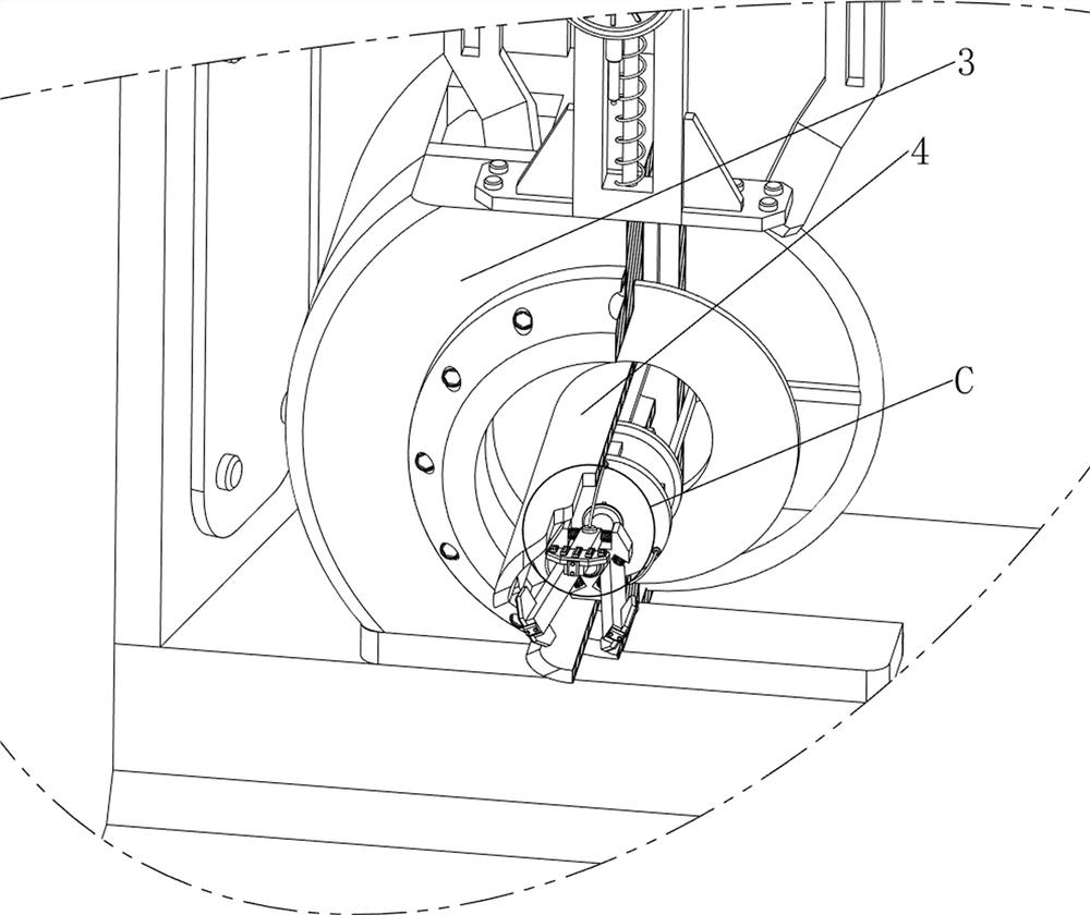
[0040] A diamond roller finished product detection device, such as figure 1 , figure 2 , image 3 , Figure 4 with Figure 5 As shown, it includes a base 1, a casing 2, a working frame 3, a rolling frame 4, a first guide frame 5, a first slider 6, a detector 7, a second slider 71, a first slider 72, and a first spring 73. The second sliding rod 8, the second spring 9, the testing mechanism 10, the fixing mechanism 11 and the rotating mechanism 12, the top of the base 1 is welded with the shell 2, and the lower part of the shell 2 is fixedly provided with the working frame 3, and the middle part of the working frame 3 passes through The way of the bearing is provided with a rolling frame 4, the front side of the top of the working frame 3 is connected with the first guide frame 5 by bolts, the second slide bar 8 is connected between the upper and lower sides of the middle part of the first guide frame 5, and the upper part of the second slide bar 8 The sliding type is prov...

Embodiment 2

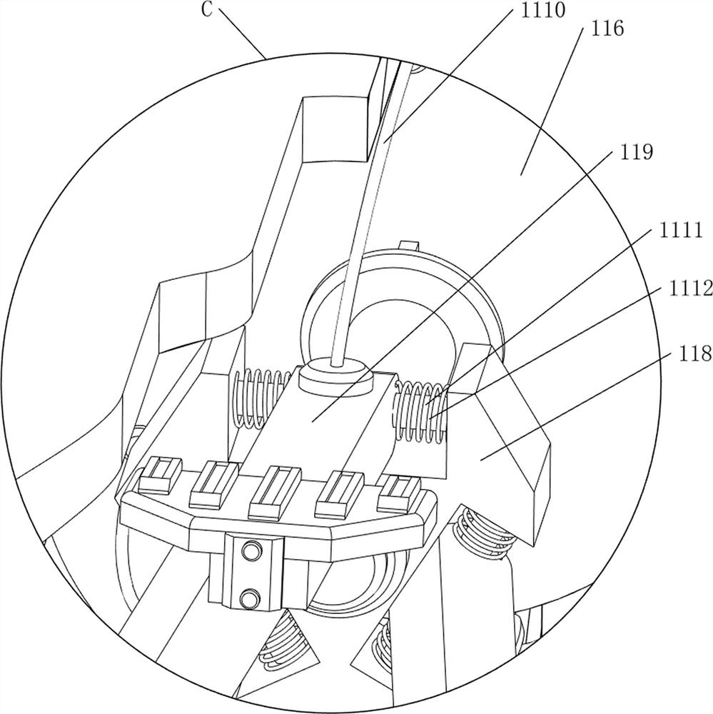
[0046] On the basis of Example 1, such as Figure 4 with Figure 12 As shown, it also includes an adapter mechanism 13, and the adapter mechanism 13 includes a telescopic rod 131, a third spring 132 and a push plate 133, and eight telescopic rods 131 are evenly spaced around the middle of the rolling frame 4, and the telescopic rods 131 A push plate 133 is connected between the telescopic ends, and a third spring 132 is wound around the telescopic rod 131 .

[0047] Due to the different sizes and specifications of the finished diamond rollers to be tested, after the finished diamond rollers are placed on the rolling frame 4, the rear side of the finished diamond rollers is in contact with the connecting rod 113, and the pressure plate 119 will push the diamond rollers when blocking the front side of the finished diamond rollers. The finished product slides backwards, and the finished product of the diamond roller can be adapted according to its size and specifications, and th...


PUM


Abstract

The invention relates to a detection device, in particular to a diamond roller finished product detection device. According to the diamond roller finished product detection device, the diamond roller can be well limited, and the credibility of the detection result is high. A diamond roller finished product detection device comprises a base, a shell, a working frame, a rolling frame, a first guide frame, a first sliding block, a second sliding rod and the like. A first guide frame is arranged on the front side of the top of the working frame, a second sliding rod is connected between the upper side and the lower side of the middle of the first guide frame, and a first sliding block is arranged on the upper portion of the second sliding rod in a sliding mode. The special-shaped block moves downwards to extrude the annular block to move backwards, so that the pressing plate can block the front side of the diamond roller finished product, the fixing and limiting effects are achieved, and the diamond roller finished product is prevented from sliding forwards and falling off in the detection process.

Description

technical field [0001] The invention relates to a detection device, in particular to a finished product detection device of a diamond roller. Background technique [0002] After the finished diamond roller is produced, in order to ensure that the diamond roller is not eccentric, it is necessary to complete the final process of the finished diamond roller: diamond roller inspection. In order to ensure that the diamond rollers that leave the factory are of qualified quality, the detection effect is generally achieved by detecting the radial circular runout data of the diamond rollers. [0003] Patent application CN212300287U, with a publication date of 20210105, discloses a finished product detection device for diamond rollers, which relates to the technical field of diamond rollers and includes a base. The bottom of the plate is screwed with a rack, and the inner bearing of the base is connected with a connecting shaft, and the connecting shaft is connected with an adjusting...

Claims


Application Information

Patent Timeline
Patent Type & Authority Applications(China)
IPC IPC(8): G01B21/00B25B11/00
CPCG01B21/00B25B11/00
Inventor 孙晖
Owner 孙晖
Why Eureka
Try Eureka