Coal bed gas detection device capable of sampling soil at different depths in well
A detection device and coalbed methane technology, which is applied in the field of coalbed methane detection, can solve the problems of inability to sample soil at different depths in the well
- Summary
- Abstract
- Description
- Claims
- Application Information
AI Technical Summary
Problems solved by technology
Method used
Image
Examples
Embodiment 1
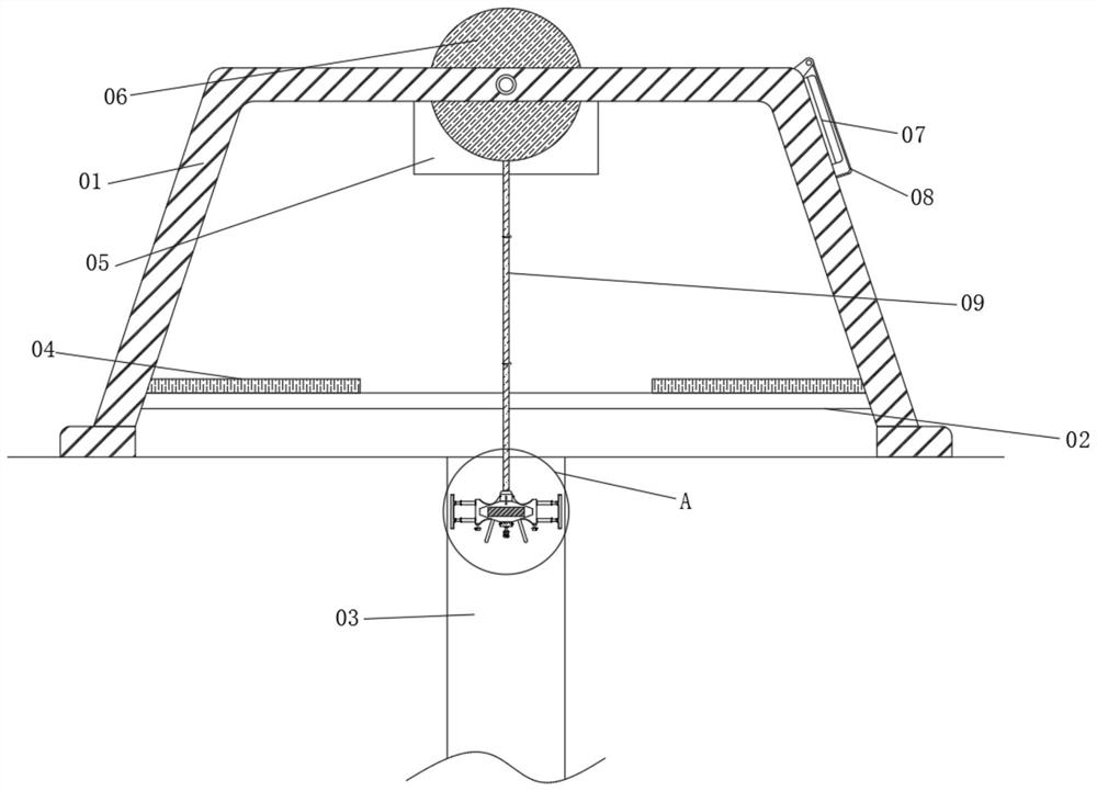
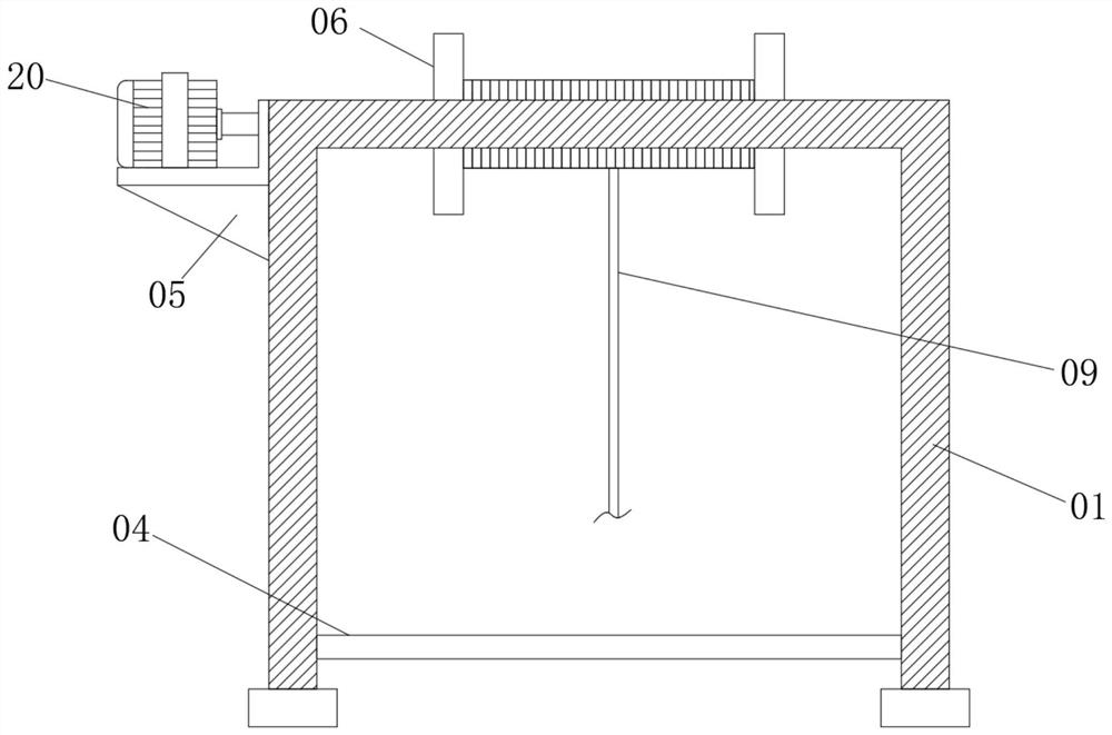
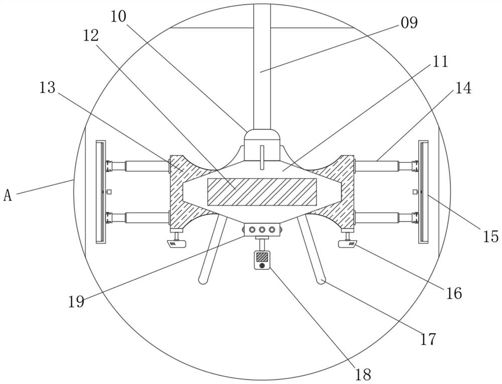
[0040] see figure 1, a coalbed methane detection device capable of sampling soil at different depths in a well according to the present invention includes a support frame 01 and a wellway 03, and a reel 06 is rotatably connected to the center of the inner side of the support frame 01 near the top. The outer surface of 06 is wound with a connecting rope 09, one end of the connecting rope 09 is fixedly connected with a butt joint 10, and the bottom end of the butt joint 10 is fixedly connected with a fixed block main body 11, and a cavity is provided in the center of the inner cavity of the fixed block main body 11; A power supply unit 12 is installed in the cavity, and the left and right sides of the fixed block main body 11 are fixedly connected with fixed block flanks 13, and the two fixed block flanks 13 are far away from each other and are fixedly installed with electric telescopic rods 14 near the top and bottom. The two sets of electric telescopic rods 14 are provided wit...
Embodiment 2
[0042] see Figure 5 , 6 , 7, the outer surface of the butt joint 10 is fixedly connected with four connecting pieces around the ring at equal distances, and the bottom surfaces of the four connecting pieces are all fixedly connected with the top surface of the fixed block main body 11. This structure is set so that the distance between the butt joint 10 and the fixed block main body 11 The connection between the two sets of electric telescopic rods 14 is fixedly connected to the first pair of insertion rods 23 at the ends far away from each other, and the two sampling frames 15 are fixedly connected to one side and corresponding to the first pair of insertion rods 23. There is a first docking socket 22 that fits with the first docking rod 23, and the first docking rod 23 is inserted into the first docking socket 22 and fixed by fixing screws. This structure allows the staff to better sample The frame 15 is disassembled and installed, or the sampling frame 15 of different len...
Embodiment 3
[0044] see image 3 The bottom of the fixed block main body 11 close to the edge is fixedly connected with three legs 17 equidistant around the ring. 11 can be better placed on the placement board 04; the central position of the bottom of the fixed block main body 11 is fixedly equipped with a light 19, and the bottoms of the two fixed block flanks 13 are fixedly installed with a camera 16. This structure is set so that the staff can Through the camera 16 and the lighting lamp 19, the situation inside the shaft 03 can be better observed; the central position of the bottom of the lighting lamp 19 is fixedly equipped with a gas detector 18, and the front of the gas detector 18 is provided with an air inlet near the bottom. The structural setting allows the staff to better detect the gas in the shaft 03; the position between the inner side of the support frame 01 near the front and back and near the bottom is fixedly connected with the crossbar 02, and the top of the two crossbar...
PUM
 Abstract
Description
Claims
Application Information
 - R&D
- Intellectual Property
- Life Sciences
- Materials
- Tech Scout
- Unparalleled Data Quality
- Higher Quality Content
- 60% Fewer Hallucinations
Browse by: Latest US Patents, China's latest patents, Technical Efficacy Thesaurus, Application Domain, Technology Topic, Popular Technical Reports.
© 2025 PatSnap. All rights reserved.Legal|Privacy policy|Modern Slavery Act Transparency Statement|Sitemap|About US| Contact US: help@patsnap.com


