Non-interception type direct current beam position and beam spot shape measurement method and system

A beam position, non-intercepting technology, applied in measurement devices, radiation measurement, X/γ/cosmic radiation measurement, etc., can solve the problems of easily damaged and ablated measurement objects, high use cost, and easy interference. To achieve the effect of simple structure, low manufacturing cost and low cost

Pending Publication Date: 2022-05-10
HEFEI INSTITUTES OF PHYSICAL SCIENCE - CHINESE ACAD OF SCI
View PDF2 Cites 0 Cited by
  • Summary
  • Abstract
  • Description
  • Claims
  • Application Information

AI Technical Summary

Problems solved by technology

[0007] The technical problem to be solved by the present invention is how to solve the technical problems of complex structure, easy to be disturbed, high cost of use, easy to be damaged and ablated, and single measurement object

Method used


Image

  • Non-interception type direct current beam position and beam spot shape measurement method and system
  • Non-interception type direct current beam position and beam spot shape measurement method and system
  • Non-interception type direct current beam position and beam spot shape measurement method and system

Examples


Embodiment 1

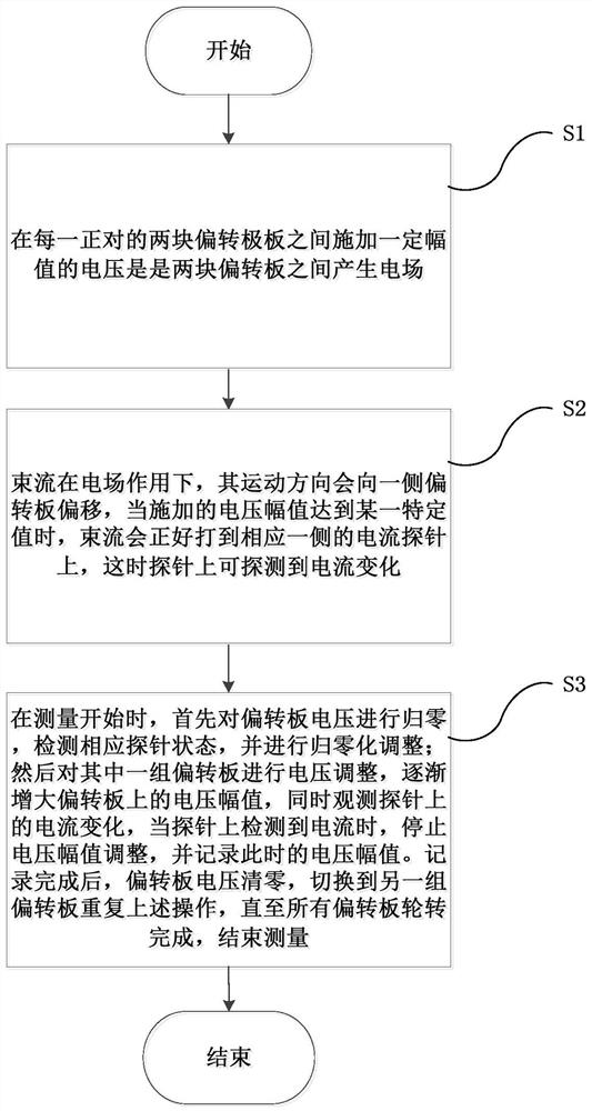
[0058] Beam position and beam spot shape measuring method of the present invention, carry out as follows:

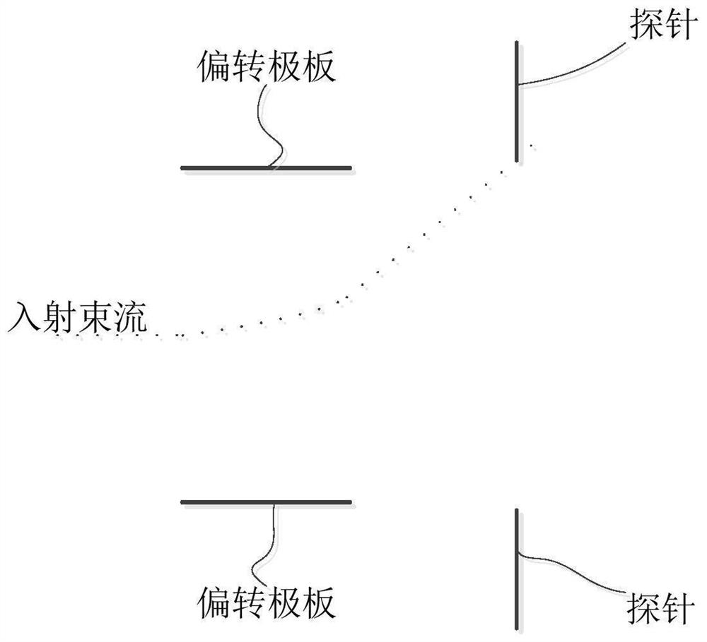
[0059] like image 3 As shown, a pulse voltage with variable amplitude can be applied between each pair of two deflecting plates to deflect the beam; the current probe can detect the deflected beam hitting the probe. The whole detection system is composed of n pairs of deflection plates and n pairs of probes. The deflection plates are arranged in a circle with the center of symmetry as the axis, and the corresponding probes are placed at a certain distance behind the deflection plates.

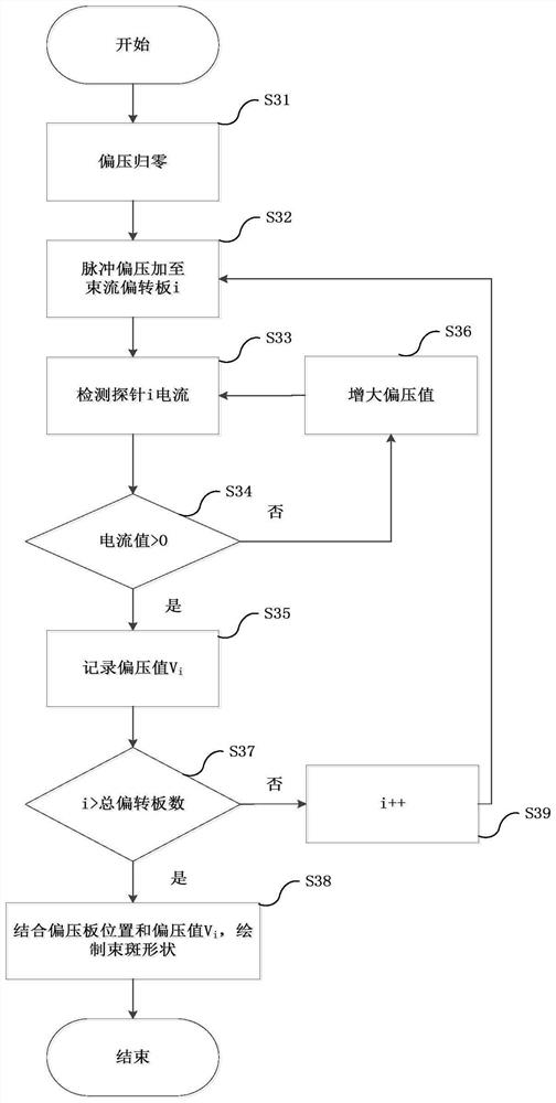
[0060] Define the amplitude of the pulse voltage applied across the deflection plate as V i , i represents the serial number of each deflection plate.

[0061] Acquisition of pulse voltage value of deflection plate

[0062] like figure 1 and Figure 4 As shown, S1, applying a voltage of a certain magnitude between each pair of two deflection plates is to generate an electric field b...


PUM


Abstract

The invention provides a non-interception type direct current beam position and beam spot shape measurement method and system. The method comprises the following steps: applying a voltage with a preset amplitude between each two opposite deflection polar plates in a measurement probe so as to generate an electric field between the two deflection polar plates; enabling the beam current to hit on a current probe through the electric field so as to detect the current change; returning the voltage of the deflection pole plates to zero, adjusting the voltage of the deflection pole plates until the current probe detects the current, recording the voltage amplitude at the moment, and circulating the operation on each group of deflection pole plates until the measurement is finished; and processing the voltage amplitude by a preset logic to obtain an offset displacement so as to obtain the beam position and the beam spot shape. The technical problems that the structure is complex, interference is likely to happen, the use cost is high, damage and ablation are likely to happen, and the measured object is single are solved.

Description

technical field [0001] The invention relates to the technical field of accelerator beam diagnosis, in particular to a method and system for measuring a non-intercepting DC beam position and beam spot shape. Background technique [0002] Beam position and beam spot shape are important parameters in the process of accelerator debugging, operation and acceptance. In order to ensure the efficient and reliable transport of particles during the operation of the accelerator system, and to provide high-quality, high-brightness and stable beams for subsequent work, a series of parameters of the beams need to be continuously optimized during system debugging and operation. Accurate and effective acquisition and diagnosis of parameters such as beam position and beam spot shape can not only greatly save the time of confinement debugging, obtain better beam quality, but also effectively reduce the failure rate of accelerator operation and improve the service life of the accelerator. [...

Claims


Application Information

Patent Timeline
Patent Type & Authority Applications(China)
IPC IPC(8): G01T1/29
CPCG01T1/29
Inventor 肖丹陈思泽章勇李桃生
Owner HEFEI INSTITUTES OF PHYSICAL SCIENCE - CHINESE ACAD OF SCI
Why Eureka
Try Eureka