
Three-dimensional imaging equipment for engineering project planning and imaging method thereof

A technology for three-dimensional imaging and engineering projects, which can be used in the use of re-radiation, instruments, installation, etc., and can solve the problems of low efficiency of measurement methods.

Pending Publication Date: 2022-05-10
江苏凯跃科技有限公司
View PDF0 Cites 0 Cited by
  • Summary
  • Abstract
  • Description
  • Claims
  • Application Information

AI Technical Summary

Problems solved by technology

[0004] The object of the present invention is to provide a kind of three-dimensional imaging equipment and its imaging method for engineering project planning, to solve the problem that the existing total station or two-dimensional end-face instrument proposed in the above-mentioned background technology can only scan one section of the tunnel at a time, and the efficiency of the measurement means lower question

Method used


Image

  • Three-dimensional imaging equipment for engineering project planning and imaging method thereof
  • Three-dimensional imaging equipment for engineering project planning and imaging method thereof
  • Three-dimensional imaging equipment for engineering project planning and imaging method thereof

Examples


Embodiment Construction

[0031] The following will clearly and completely describe the technical solutions in the embodiments of the present invention with reference to the accompanying drawings in the embodiments of the present invention. Obviously, the described embodiments are only some, not all, embodiments of the present invention.

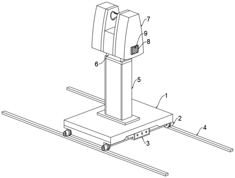
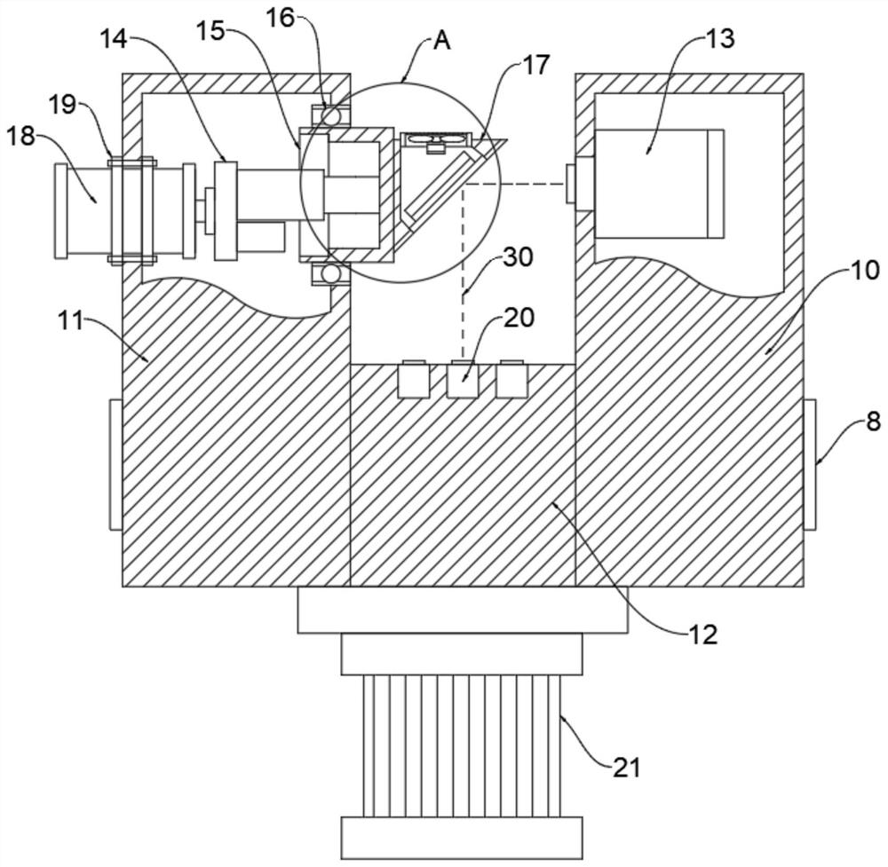
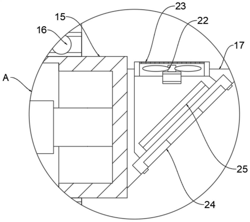
[0032] see Figure 1-6, an embodiment provided by the present invention: a three-dimensional imaging device for engineering project planning, comprising a track flat car base 1, track wheels 2 are installed on both sides of the track flat car base 1, and the track wheels 2 are provided with four , an electrical box 3 is installed below the front end of the rail flat car base 1, a support frame 5 is installed on the upper end of the rail flat car base 1, a rotating base 6 is installed on the upper end of the supporting frame 5, and a three-dimensional scanning device is installed on the upper end of the rotating base 6 7, the three-dimensional scanner 7 includes a lef...


PUM


Abstract

The invention discloses three-dimensional imaging equipment for engineering project planning and an imaging method of the three-dimensional imaging equipment, relates to the technical field of engineering project planning measurement, and aims to solve the problems that an existing total station or a two-dimensional end face instrument can only scan one section of a tunnel at a time, and the measurement means is low in efficiency. The rail flat car comprises a rail flat car base, four rail wheels are installed on each of the two sides of the rail flat car base, an electrical cabinet is installed below the front end of the rail flat car base, a supporting frame is installed at the upper end of the rail flat car base, a rotating base is installed at the upper end of the supporting frame, and a three-dimensional scanner is installed at the upper end of the rotating base. The three-dimensional scanner comprises a left cavity, a connecting cavity and a right cavity, the connecting cavity is arranged between the left cavity and the right cavity, and the two ends of the connecting cavity are communicated with the left cavity and the right cavity respectively.

Description

technical field [0001] The invention relates to the technical field of engineering project planning and measurement, in particular to a three-dimensional imaging device for engineering project planning and an imaging method thereof. Background technique [0002] In the project planning stage of tunnel engineering, in order to confirm the current tunnel disease problems, it is often necessary to use scanning equipment to collect three-dimensional imaging of the tunnel, mainly relying on total stations or two-dimensional end-face instruments. [0003] However, the total station or the two-dimensional end-face instrument can only scan one section of the tunnel at a time, and the efficiency of the measurement method is low; therefore, we propose a three-dimensional imaging device and its imaging method for engineering project planning, in order to solve the problems mentioned above. question. Contents of the invention [0004] The object of the present invention is to provide...

Claims


Application Information

Patent Timeline
IPC IPC(8): G02B26/10G02B7/18G02B7/198G01S17/894G01S17/08G01S7/481
CPCG02B26/105G02B7/1815G02B7/1821G01S17/894G01S17/08G01S7/4817G01S7/481
Inventor 吴志凯杨珊
Owner 江苏凯跃科技有限公司
Features
  • Generate Ideas
  • Intellectual Property
  • Life Sciences
  • Materials
  • Tech Scout
  • Unparalleled Data Quality
  • Higher Quality Content
  • 60% Fewer Hallucinations
Learn More