
Power installation pipeline laying device and laying method

A technology for laying devices and pipes, applied to cable laying equipment and other directions, can solve the problems of inconvenient control, easy bending of pipes, inconvenient pipes, etc., and achieve the effect of improving fixing effect, improving installation effect and convenient use.

Pending Publication Date: 2022-05-10
广州中创建筑科技有限公司
View PDF0 Cites 0 Cited by
  • Summary
  • Abstract
  • Description
  • Claims
  • Application Information

AI Technical Summary

Problems solved by technology

[0003] In the process of laying the existing power pipes, due to the need to lay multi-row and multi-layer pipes, the general workers use pre-opened holes for support, so it is inconvenient to control when laying pipes of different heights , and it is very inconvenient to install pipes with different rows, and when the pipes are installed, due to the relatively long main body of the pipes, the pipes are prone to bending, which reduces the installation effect of the pipes. The device with fixed pipe position increases the efficiency of pipe laying

Method used


Image

  • Power installation pipeline laying device and laying method
  • Power installation pipeline laying device and laying method
  • Power installation pipeline laying device and laying method

Examples


Embodiment Construction

[0037] The following will clearly and completely describe the technical solutions in the embodiments of the present invention with reference to the accompanying drawings in the embodiments of the present invention. Obviously, the described embodiments are only some, not all, embodiments of the present invention. All other embodiments obtained by persons of ordinary skill in the art based on the embodiments of the present invention belong to the protection scope of the present invention.

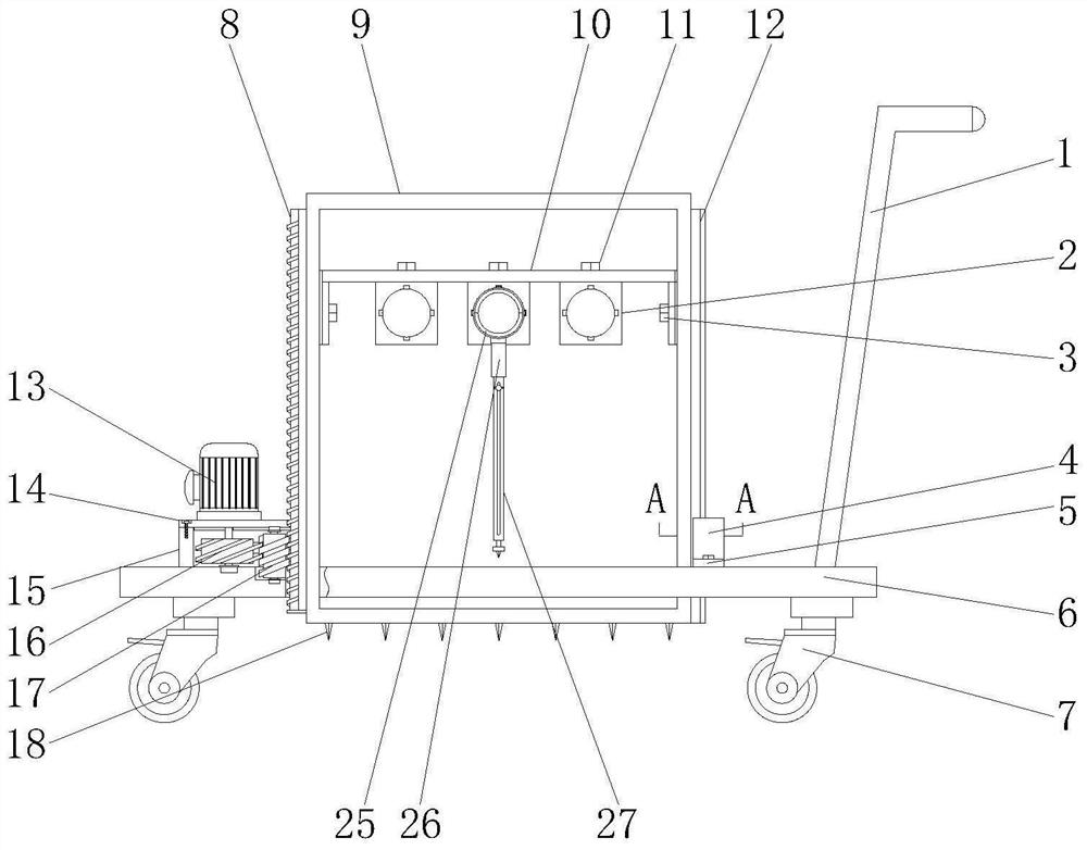
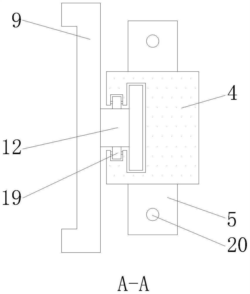
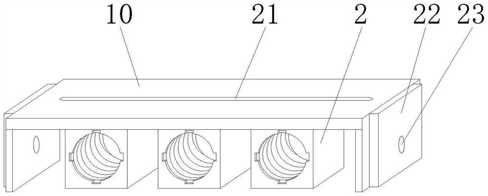
[0038] The present invention provides a power installation pipeline laying device and laying method, comprising: a moving base 6, the upper end of the moving base 6 is provided with a base push rod 1, and the lower end of the moving base 6 is provided with a universal self-locking wheel 7, and the moving base There is a rectangular through hole in the center of 6, and the inner side of the central through hole of the mobile base 6 is provided with a groove that matches the external shape of th...


PUM


Abstract

The invention discloses an electric power installation pipeline laying device and laying method.The electric power installation pipeline laying device comprises a movable base, a base push rod is arranged at the upper end of the movable base, universal self-locking wheels are arranged at the lower end of the movable base, and a rectangular through hole is formed in the center of the movable base; a transmission box and a sliding rail fixing base are fixed to the two sides above a rectangular through hole of the movable base respectively, an outer fixing frame is arranged in a central through hole of the movable base, the outer portion of the outer fixing frame is rectangular, the center of the outer fixing frame is in a rectangular through hole shape, and a fixing lead screw is arranged on the side, close to the transmission box, of the outer fixing frame. The pipeline fixing structures are arranged in the device, the position of a pipeline can be fixed, meanwhile, the pipeline fixing structures of the device can be adjusted, the position of the pipeline can be conveniently set, and the positions and the number of the pipeline fixing structures of the device can be adjusted; in this way, different numbers of pipelines can be laid quickly, and workers can use the pipeline laying device conveniently.

Description

technical field [0001] The invention relates to the technical field of electric equipment installation, in particular to a laying device and a laying method for electric installation pipelines. Background technique [0002] The power pipe is a product made of PE (modified polyethylene) for hot-dipping or epoxy resin for internal and external coating, and has excellent corrosion resistance. At the same time, the coating itself has good electrical insulation and will not cause electrical corrosion. Low water absorption, high mechanical strength, small friction coefficient, can achieve the purpose of long-term use. It can also effectively prevent damage to plant roots and soil environmental stress. [0003] During the laying of existing power pipes, due to the need to lay multi-row and multi-layer pipes, the general work is manually supported by plates with pre-opened holes, which is inconvenient to control when laying pipes of different heights , and it is very inconvenient...

Claims


Application Information

Patent Timeline
Patent Type & Authority Applications(China)
IPC IPC(8): H02G1/08
CPCH02G1/08
Inventor 邹锦新
Owner 广州中创建筑科技有限公司
Learn More