Hardware stamping device with positioning structure

A technology of stamping device and positioning structure, applied in the field of metal stamping, can solve the problems of operator injury, high replacement cost, hidden safety hazards, etc., and achieve the effect of simple and convenient operation, low cost, and avoiding mutual friction

Pending Publication Date: 2022-05-13
钟华
View PDF0 Cites 0 Cited by
  • Summary
  • Abstract
  • Description
  • Claims
  • Application Information

AI Technical Summary

Problems solved by technology

[0002] Metal stamping is a process that uses punches and molds to deform or break stainless steel, iron, aluminum, copper and other plates and heterogeneous materials to achieve a certain shape and size. Metal stamping is accompanied by uninterrupted development during the operation process. Combined reciprocating operation, in order to avoid excessive offset between the punch and the mold, a plurality of positioning rods and sleeves will be set on the four sides for downward positioning and auxiliary guidance, but the positioning rods and sleeves in the prior art are used for a long time. During the reciprocating friction operation, the main body will be seriously worn, and the cost of direct replacement is high, and the temperature of the positioning rod that is repeatedly rubbed during the operation is high, which may cause accidental damage to the operator, and there is a certain safety hazard

Method used


Image

  • Hardware stamping device with positioning structure
  • Hardware stamping device with positioning structure
  • Hardware stamping device with positioning structure

Examples


Embodiment Construction

[0028] The following will clearly and completely describe the technical solutions in the embodiments of the present invention with reference to the accompanying drawings in the embodiments of the present invention. Obviously, the described embodiments are only some, not all, embodiments of the present invention. Based on the embodiments of the present invention, all other embodiments obtained by persons of ordinary skill in the art without making creative efforts belong to the protection scope of the present invention.

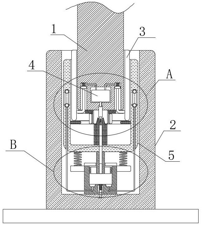
[0029] see Figure 1-5 , the present invention provides a metal stamping device with its own positioning structure: the metal stamping device includes:

[0030] The positioning column 1, the positioning column 1 is a cylindrical structure with a smooth surface, the sleeve column 2, the upper end of the sleeve column 2 is provided with a positioning groove, and the lower end of the positioning column 1 is inserted into the sleeve column 2, the pressurization co...


PUM


Abstract

The invention relates to the technical field of hardware stamping, in particular to a hardware stamping device with a positioning structure, which comprises a positioning column and a sleeve column, the positioning column is of a cylindrical structure with a smooth surface, a positioning groove is formed in the upper end of the sleeve column, and a pressurizing cylinder and a movable cylinder are respectively arranged on the contact sides of the positioning column and the sleeve column. Mutual friction between the main bodies is avoided during reciprocating positioning movement, so that after long-time use, only the pressurizing cylinder and the movable cylinder need to be detached and replaced, cost is low, use is convenient, a good heat dissipation effect is provided through the movable pressurizing cylinder and the movable cylinder, and meanwhile under the pressurizing effect of the pressurizing cylinder, the heat dissipation effect is good. Lubricating oil automatically lubricates the whole body through the mist ring and the lubricating hole, the operation is simple and convenient, and meanwhile, when the lubricating oil does not need to be added, air generated by the pressurizing cylinder can accelerate air flow in the sleeve column, so that the personal safety of operators is prevented from being influenced by overheating.

Description

technical field [0001] The invention relates to the technical field of metal stamping, in particular to a metal stamping device with a positioning structure. Background technique [0002] Metal stamping is a process that uses punches and molds to deform or break stainless steel, iron, aluminum, copper and other plates and heterogeneous materials to achieve a certain shape and size. Metal stamping is accompanied by uninterrupted development during the operation process. Combined reciprocating operation, in order to avoid excessive offset between the punch and the mold, a plurality of positioning rods and sleeves will be set on the four sides for downward positioning and auxiliary guidance, but the positioning rods and sleeves in the prior art are used for a long time. During the reciprocating friction operation, the main body will be severely worn, and the cost of direct replacement will be high, and the temperature of the positioning rod that is repeatedly rubbed during the ...

Claims


Application Information

Patent Timeline
Patent Type & Authority Applications(China)
IPC IPC(8): B21D37/18
CPCB21D37/18
Inventor 钟华
Owner 钟华
Why Eureka
Try Eureka