
Cylinder cover forming die

A technology for forming molds and cylinder heads, which is applied to casting and forming equipment, cores, casting molds, etc., can solve the problem of inconvenient cylinder head removal, and achieve the effect of convenient removal.

Pending Publication Date: 2022-05-13
华威钜全压铸(三明)有限公司
View PDF9 Cites 0 Cited by
  • Summary
  • Abstract
  • Description
  • Claims
  • Application Information

AI Technical Summary

Problems solved by technology

[0005] Although the above case can be replaced by manual disassembly by the ejector mechanism, the ejector mechanism can only push the upper box and the lower box apart, and it is still inconvenient to take out the formed cylinder head. Therefore, a cylinder head forming mold is designed. It is necessary to solve the above problems

Method used


Image

  • Cylinder cover forming die
  • Cylinder cover forming die
  • Cylinder cover forming die

Examples


Embodiment Construction

[0019] The following will clearly and completely describe the technical solutions in the embodiments of the present invention with reference to the accompanying drawings in the embodiments of the present invention. Obviously, the described embodiments are only some, not all, embodiments of the present invention. Based on the embodiments of the present invention, all other embodiments obtained by persons of ordinary skill in the art without making creative efforts belong to the protection scope of the present invention.

[0020] In describing the present invention, the terms "up", "down", "left", "right", "front", "rear", "top", "bottom" and the like indicate an orientation or state unless otherwise specified The relationship is based on the orientation or state relationship shown in the drawings, and it is only for the convenience of describing the present invention and simplifying the description, rather than indicating or implying that the mechanism or component referred to m...


PUM


Abstract

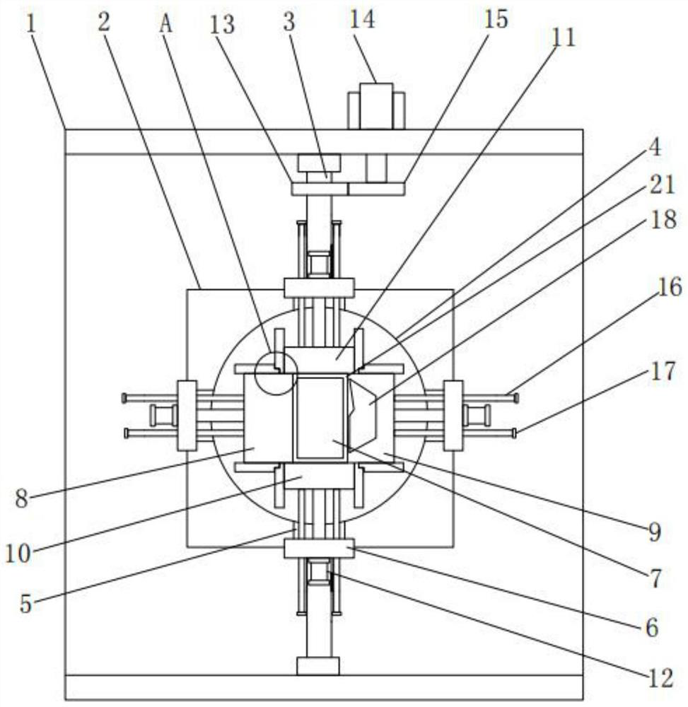
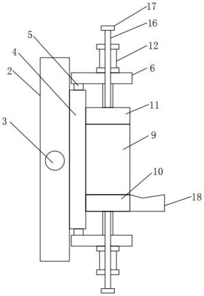
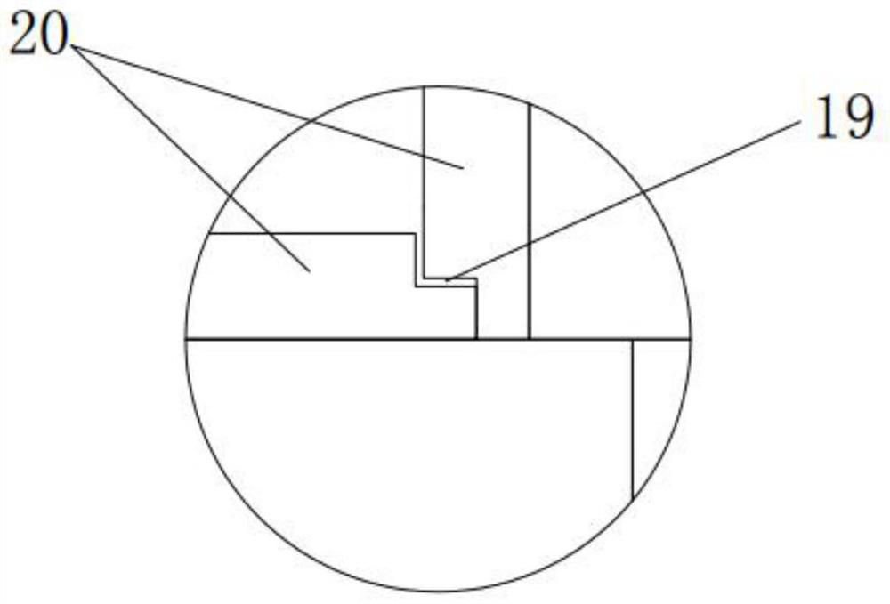
The invention discloses a cylinder cover forming mold which comprises a mold frame, a bottom plate is arranged in the center of the interior of the mold frame, a pouring circular truncated cone is installed above the bottom plate, a bottom mold plate is arranged at the top of the pouring circular truncated cone, a first side mold plate is arranged on the left side of the bottom mold plate, and a second side mold plate is arranged on the right side of the bottom mold plate. A third side mold plate is arranged on the front side of the bottom mold plate, a fourth side mold plate is arranged on the rear side wall of the bottom mold plate, an air cylinder is installed on the outer side wall of each air cylinder installation base, a telescopic rod of the air cylinder at the left end is connected with the first side mold plate, and a telescopic rod of the air cylinder at the right end is connected with the second side mold plate. The air cylinders are started to drive the telescopic rods of the air cylinders to be shortened, so that the first side mold plate, the second side mold plate, the third side mold plate and the fourth side mold plate can move towards the outer side of the bottom mold plate, and the poured cylinder cover can be conveniently taken out.

Description

technical field [0001] The invention belongs to the technical field of cylinder head molding dies, in particular to a cylinder head molding die. Background technique [0002] The cylinder head is a part of the automobile engine, usually made of cast iron or aluminum alloy, it is the installation base of the valve mechanism, and it is also the sealing cover of the cylinder. The damage phenomena of the cylinder head are mostly warping deformation of the sealing plane between the cylinder head and the cylinder hole (destroying the seal), cracks in the seat holes of the intake and exhaust valves, damage to the spark plug installation thread, etc., especially the cylinder head made of aluminum alloy. Because of its low hardness and relatively poor strength, the material is relatively easy to deform and damage. [0003] Cylinder head production technology usually uses sand molds. After the sand mold is formed, the sand box needs to be removed. At this time, because the structure ...

Claims


Application Information

Patent Timeline
Patent Type & Authority Applications(China)
IPC IPC(8): B22C9/22B22C9/02B22D29/06
CPCB22C9/22B22C9/02B22D29/06
Inventor 赵洪全
Owner 华威钜全压铸(三明)有限公司
Learn More