Grinding and separating device of plain end vibration polisher machine

A technology of separation device and finishing machine, which is applied in the field of finishing machines, can solve the problems of increased maintenance and use costs, insufficient safety and stability, inability to operate separation, etc., so as to improve the safety of use, facilitate vibration operation, and ensure the stability of use Effect

Pending Publication Date: 2022-05-13
张伟伟
View PDF0 Cites 1 Cited by
  • Summary
  • Abstract
  • Description
  • Claims
  • Application Information

AI Technical Summary

Problems solved by technology

[0003] However, most of the existing separation devices for finishing machines use the rack to install the processing box, and then connect the vibrating components to operate. In this way, the separation type needs to take out the workpiece and the abrasive synchronously, and then separate them through the screening device, which cannot be directly separated. It is cumbersome to operate and separate on the finishing machine, and the efficiency is low, and it is easy to leave and lose abrasives, which increases the cost of maintenance and use. At the same time, when the vibration operation of the processing box is performed, it is easy to cause the base to vibrate synchronously, and the safety and stability are insufficient, which needs to be improved.

Method used


Image

  • Grinding and separating device of plain end vibration polisher machine
  • Grinding and separating device of plain end vibration polisher machine
  • Grinding and separating device of plain end vibration polisher machine

Examples


Embodiment Construction

[0031] The following will clearly and completely describe the technical solutions in the embodiments of the present invention in conjunction with the accompanying drawings in the embodiments of the present invention; obviously, the described embodiments are only part of the embodiments of the present invention, not all embodiments, based on The embodiments of the present invention and all other embodiments obtained by persons of ordinary skill in the art without making creative efforts belong to the protection scope of the present invention.

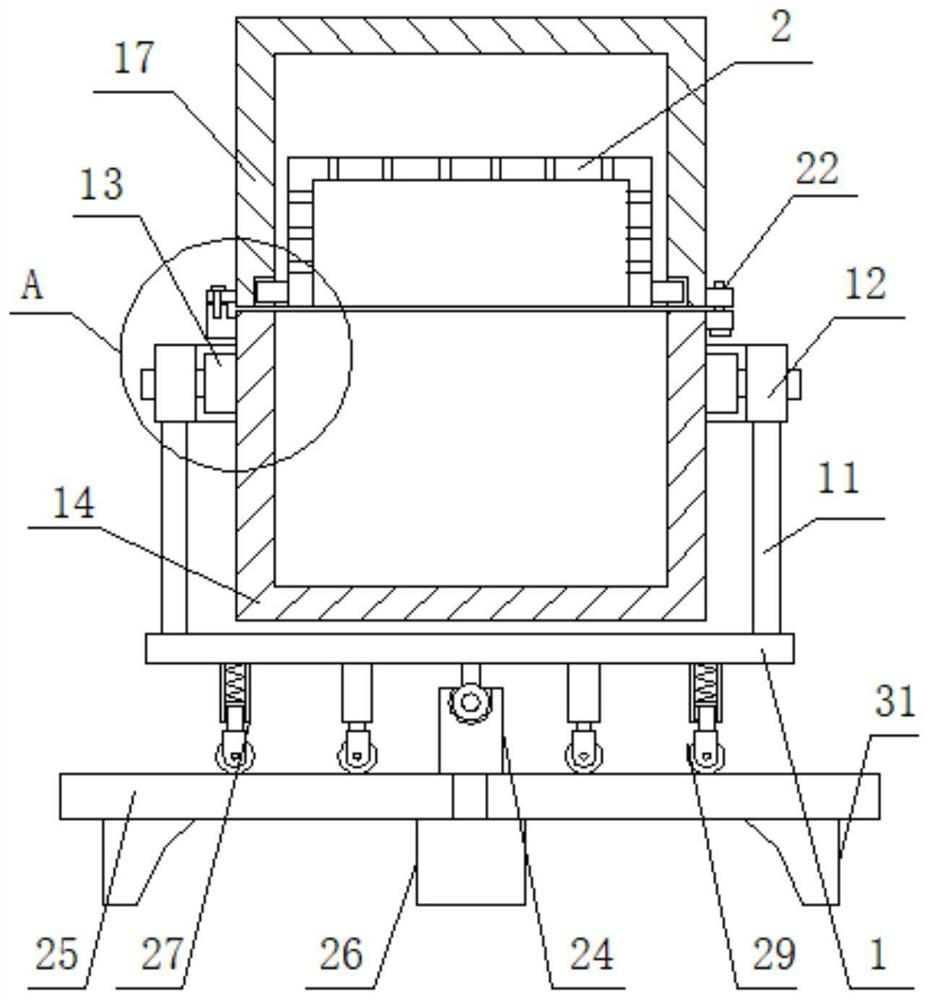
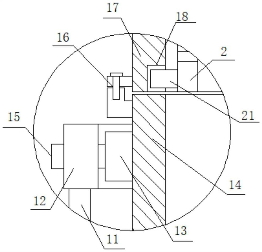
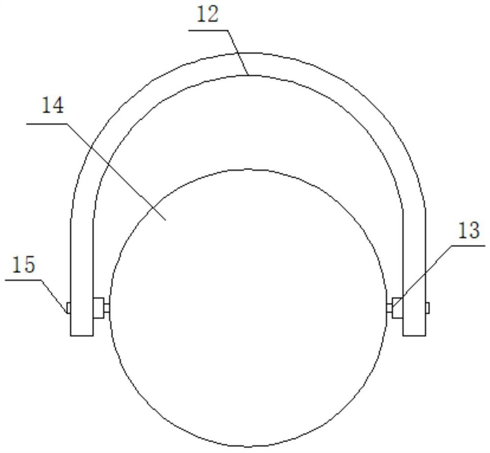
[0032] see Figure 1-4 , an abrasive and separating device for a flat vibrating finisher, including a mounting plate 1, please refer to figure 1 , figure 2 and image 3 , both ends of one side surface of the mounting plate 1 are fixedly connected with a fixed rod 11, one end of the fixed rod 11 is fixedly connected with a U-shaped frame 12, and both sides of the U-shaped frame 12 are rotatably connected with a transverse shaft 13, whi...


PUM


Abstract

The invention discloses a grinding and separating device of a plain end vibration polisher machine, which comprises a mounting plate, fixing rods are fixedly connected to the two ends of the surface of one side of the mounting plate, a U-shaped frame is fixedly connected to one end of each fixing rod, transverse shafts are rotatably connected to the surfaces of the two sides of the U-shaped frame, and a treatment box is rotatably connected to the surfaces of the transverse shafts; positioning screws are in threaded connection with the two ends of the surface of the other side of the U-shaped frame, one ends of the positioning screws abut against and are connected to the surface of the transverse shaft, a transverse hinge seat is hinged to the side face of one end of the treatment box, a separation box is hinged to the surface of the transverse hinge seat, and an opening in one end of the separation box is slidably connected to the surface of one end of the treatment box; a positioning groove is formed in a port of the separation box, a mesh box is slidably connected to the side face of the separation box, and a positioning ring is fixedly connected to the side face of one end of the mesh box, so that the practical convenience and stability can be greatly improved, and safety and high efficiency of separation and operation are guaranteed.

Description

technical field [0001] The invention relates to the field of finishing machines, and more specifically, relates to an abrasive material and separating device of a flat vibrating finishing machine. Background technique [0002] When using the vibrating finishing machine to take out the workpiece, it is necessary to mix the abrasive and the workpiece, then vibrate the work, and finally separate it through the separation device to take out the workpiece. [0003] However, most of the existing separation devices for finishing machines use the rack to install the processing box, and then connect the vibrating components to operate. In this way, the separation type needs to take out the workpiece and the abrasive synchronously, and then separate them through the screening device, which cannot be directly separated. It is cumbersome to operate and separate on the finishing machine, and the efficiency is low, and it is easy to leave and lose the abrasive, which increases the cost of...

Claims


Application Information

Patent Timeline
Patent Type & Authority Applications(China)
IPC IPC(8): B24B31/16B07B1/00
CPCB24B31/16B07B1/00
Inventor 不公告发明人
Owner 张伟伟
Why Eureka
Try Eureka