Rocket engine turnover mechanism

A rocket engine and flipping mechanism technology, applied in the direction of lifting frame, lifting device, etc., can solve the problems of difficult expansion and application of different types of engines, complex structure, etc., and achieve the effect of simple structure, simple switching, and elimination of meshing gap

Pending Publication Date: 2022-05-13
武汉天拓宇航智能装备有限公司
View PDF0 Cites 0 Cited by
  • Summary
  • Abstract
  • Description
  • Claims
  • Application Information

AI Technical Summary

Problems solved by technology

Although there is an overturning mechanism that can realize the above functions in the prior art, the structure is complex, so it is difficult to expand the application for different types of engines

Method used


Image

  • Rocket engine turnover mechanism
  • Rocket engine turnover mechanism
  • Rocket engine turnover mechanism

Examples


Embodiment Construction

[0028] The following will clearly and completely describe the technical solutions in the embodiments of the present invention in conjunction with the embodiments of the present invention. Obviously, the described embodiments are only part of the embodiments of the present invention, not all of them. Based on the implementation manners in the present invention, all other implementation manners obtained by persons of ordinary skill in the art without making creative efforts belong to the scope of protection of the present invention.

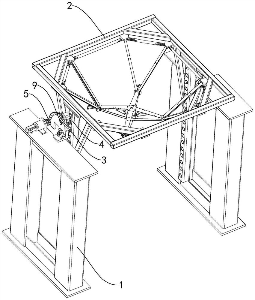
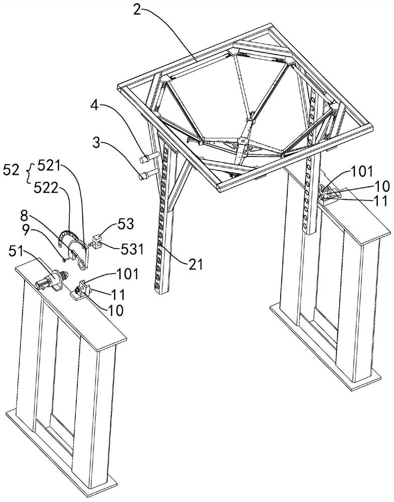
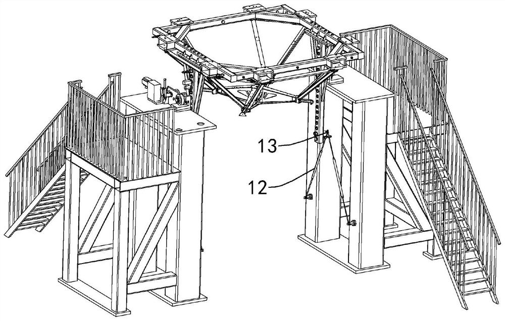
[0029] Such as figure 1 shown, combined with Figure 2-5 , the rocket engine overturning mechanism of the present invention, it comprises support column 1, fixed frame 2, rotating shaft 3, shift block 4 and driving device 5, and support column 1 is symmetrically arranged on the opposite two ends of fixed frame 2, and fixed frame 2 is used for The rocket engine is fixed, and the side of the fixed frame 2 close to the support column 1 is provided wi...


PUM


Abstract

The rocket engine turnover mechanism comprises supporting columns, a fixing frame, rotating shafts, shifting blocks and a driving device, the supporting columns are symmetrically arranged at the two opposite ends of the fixing frame, the fixing frame is used for fixing a rocket engine, the rotating shafts are arranged on the side faces, close to the supporting columns, of the fixing frame, and the rotating shafts abut against the supporting columns; the fixing frame can rotate around the rotating shaft, the driving device is fixedly installed on one supporting column, a shifting block is arranged on the side, close to the driving device, of the fixing frame, and the driving device is selectively in transmission connection with the shifting block and can drive the fixing frame to rotate around the rotating shaft. According to the turnover mechanism, the fixing frame can be conveniently detached and adjusted, and therefore the turnover mechanism can be suitable for turnover operation of engines of different models.

Description

technical field [0001] The invention relates to the technical field of aviation equipment production, in particular to a rocket engine turning mechanism. Background technique [0002] During the process of assembly and transportation, the rocket engine needs to adjust its attitude many times, and the rocket engine is mostly assembled in a vertical state. In order to facilitate transportation and delivery, the engine will be flipped horizontally as a whole. During the flip process, many requirements are put forward for the equipment. [0003] For example, the fixing method between the turning system and the ground should be as simple as possible to avoid damage to the ground. Secondly, during the turning process, the engine should remain stable as a whole, the turning speed should be electrically controlled, and hovering at any angle should be possible during the turning process. and lock function. Although there is an overturning mechanism capable of realizing the above fun...

Claims


Application Information

Patent Timeline
Patent Type & Authority Applications(China)
IPC IPC(8): B66F7/22B66F7/28
CPCB66F7/22B66F7/28
Inventor 许冶高志强万建武涂克恒柏俊松
Owner 武汉天拓宇航智能装备有限公司
Why Eureka
Try Eureka