

Deep foundation pit supporting structure
A deep foundation pit support and foundation pit technology, applied in infrastructure engineering, construction, excavation, etc., can solve the problems of inconvenient disassembly, achieve the effect of convenient disassembly process and improve work efficiency
- Summary
- Abstract
- Description
- Claims
- Application Information
AI Technical Summary
Problems solved by technology
Method used
Image

Examples
Embodiment 1
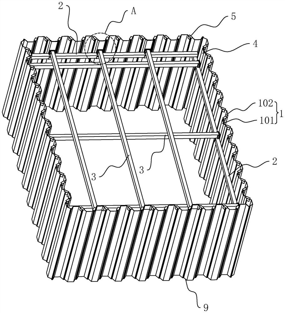
[0040] The embodiment of the present application discloses a support structure for a deep foundation pit. refer to figure 1 and figure 2 , deep foundation pit support structure. It includes steel sheet piles 1 arranged continuously along the inner wall of the foundation pit, and each steel sheet pile 1 forms a closed-loop retaining wall 9 together. The retaining wall 9 has a square structure as a whole. The four inner surfaces of the retaining wall 9 A support beam 2 is provided, and a plurality of mutually parallel cross-stay beams 3 are jointly erected between two opposite support beams 2, wherein the cross-stay beams 3 of different orientations are arranged vertically in dislocation; the support beams 2 The upper surface is fixedly connected with a plurality of push plates 21 corresponding to the ends of the cross-bracing beams 3, and the cross-bracing beams 3 are used to force the opposing push plates 21 to move away from each other.
[0041] refer to figure 1 , the su...
Embodiment 2
[0055] refer to Figure 5 and Figure 6 The difference between this embodiment and Embodiment 1 is that: a clamping assembly 8 is connected between the two ends of the cross brace beam 3 and the two opposite support beams 2, and the clamping assembly 8 includes a first clamping block 81, The second clamping block 82 and the sleeve 83;
[0056] The sleeve 83 is sleeved and connected to the end of the first cross brace 3, and one end of the sleeve 83 is closed, and the first clamping block 81 is fixedly connected to the closed end of the sleeve 83, and a plurality of pads are placed inside the sleeve 83. Plates 84, each backing plate 84 is dislocated along the length direction of the cross brace 3, and the backing plate 84 is located between the end faces of the second clamping block 82 of the cross brace 3; the second clamping block 82 is fixedly connected with the push plate 21, The first clamping block 81 and the second clamping block 82 are dislocated along the length dire...
PUM
 Abstract
Description
Claims
Application Information