Online detection system and detection method for hydraulic equipment

A technology of hydraulic equipment and detection system

Active Publication Date: 2022-05-13
CHINA THREE GORGES CORPORATION
View PDF7 Cites 0 Cited by
  • Summary
  • Abstract
  • Description
  • Claims
  • Application Information

AI Technical Summary

Problems solved by technology

[0003] Therefore, the technical problem to be solved by the present invention lies in the problem existing in the prior art that hydraulic system flow detection requires the opening and closing of the gate, thereby providing an online detection system and detection method for hydraulic equipment

Method used


Image

  • Online detection system and detection method for hydraulic equipment
  • Online detection system and detection method for hydraulic equipment
  • Online detection system and detection method for hydraulic equipment

Examples


Embodiment 1

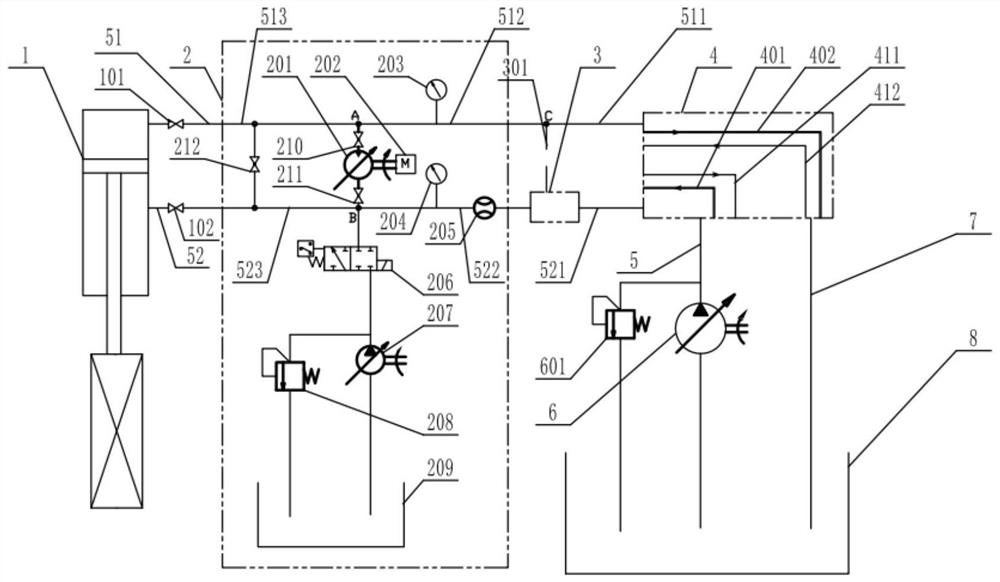
[0070] Such as figure 1 As shown, the embodiment of the present invention provides an online detection system for hydraulic equipment. The online detection system for hydraulic equipment includes: a hydraulic cylinder 1 , a hydraulic control system, and a detection circuit 2 .

[0071] Specifically, the hydraulic cylinder 1 is used to open and close the gate, and the hydraulic cylinder 1 has a rodless cavity and a rod cavity; the hydraulic control system communicates with the rodless cavity through a rodless cavity pipeline 51, The hydraulic control system communicates with the rod chamber through the rod chamber pipeline 52, and the rodless chamber pipeline 51 and the rod chamber pipeline 52 are respectively provided with a rodless chamber valve 101 and a rod chamber pipeline. chamber valve 102; the detection circuit 2 includes a hydraulic motor 201 and a communication valve 212 respectively arranged in parallel with the hydraulic cylinder 1, and the communication valve 212 i...

Embodiment 2

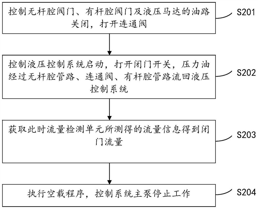
[0100] Such as Figure 1 to Figure 4 As shown, the embodiment of the present invention provides an online detection method for hydraulic equipment, and the online detection method includes the online detection system for hydraulic equipment described in Embodiment 1 above.

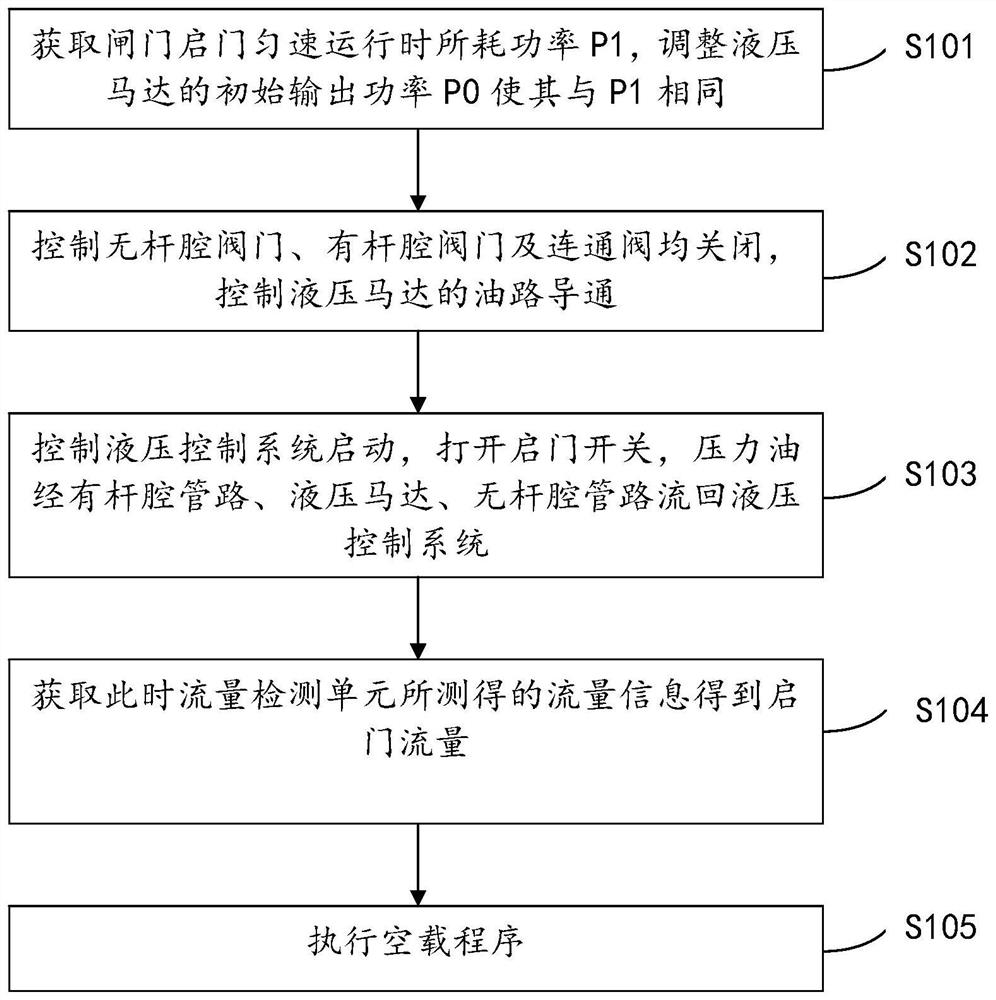
[0101] In the first implementation of this embodiment, the hydraulic equipment online detection method includes door opening pressure, flow (speed) detection method, combined with figure 1 , figure 2 As shown, the door opening flow detection method includes:

[0102] Execute the door opening detection program, which specifically includes the following steps:

[0103] S101: Obtain the power P1 consumed when the gate is opened at a constant speed, and adjust the initial output power P0 of the hydraulic motor 201 to be the same as P1;

[0104] S102: control the non-rod chamber valve 101, the rod chamber valve 102 and the communication valve 212 to be closed, and control the conduction of the oil circuit o...


PUM


Abstract

The invention discloses a hydraulic equipment on-line detection system which comprises a hydraulic cylinder, a hydraulic motor and a communication valve, the hydraulic motor and the communication valve are connected with the hydraulic cylinder in parallel, and the communication valve is connected between a rodless cavity pipeline and a rod cavity pipeline. The initial output power of the hydraulic motor is the same as the power consumed when the gate is opened and runs at a constant speed; the detection loop comprises a hydraulic motor and a communication valve, the hydraulic motor and the communication valve are connected with the hydraulic cylinder in parallel, and the communication valve is connected between the rodless cavity pipeline and the rod cavity pipeline; the detection loop comprises a flow detection unit, and the flow detection unit is arranged on a rod cavity pipeline or a rodless cavity pipeline between the hydraulic motor and the hydraulic control system. By means of the arrangement, flow detection in the hydraulic equipment can be achieved under the condition that the gate is not opened, coordination work in the gate opening and closing process is reduced, the risk of water drainage is reduced, and meanwhile the problem of water resource waste is solved.

Description

technical field [0001] The invention relates to the technical field of water conservancy, hydropower and hydraulic equipment, in particular to an online detection system and detection method for hydraulic equipment. Background technique [0002] In water conservancy and hydropower projects, the hydraulic system can control the opening and closing of the gate. In order to ensure the normal operation of the gate, it is necessary to regularly detect the working status of the hydraulic system to ensure that the pressure and flow of the system or the speed of opening and closing the door are normal. However, the existing hydraulic system Flow detection needs to open and close the gate to carry out. Therefore, it is necessary to spend a lot of manpower to coordinate the personnel of relevant units in the river basin to take measures to release water, and at the same time, the water volume in the reservoir area of ​​the hydropower station will be wasted. Contents of the invention...

Claims


Application Information

Patent Timeline
Patent Type & Authority Applications(China)
IPC IPC(8): F15B19/00F15B20/00
CPCF15B19/00F15B20/005F15B2211/857F15B2211/863Y02E10/20
Inventor 董彦同高潮贺小平李亚军官文邓伦
Owner CHINA THREE GORGES CORPORATION
Why Eureka
Try Eureka