Power test method for N-type battery assembly
A battery component and power testing technology, applied in the field of solar cells, can solve problems such as measuring N-type battery components, and achieve the effects of eliminating capacitance effect, easy operation, and simple method.
- Summary
- Abstract
- Description
- Claims
- Application Information
AI Technical Summary
Problems solved by technology
Method used
Image

Examples
Embodiment 1
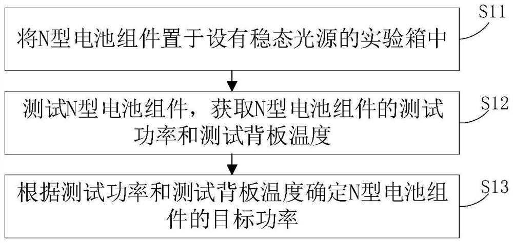
[0023] see figure 1 , the power testing method of the N-type battery assembly of the embodiment of the present application, comprising:
[0024] Step S11: placing the N-type battery assembly in an experiment box provided with a steady-state light source;
[0025] Step S12: test the N-type battery assembly, obtain the test power and test backplane temperature of the N-type battery assembly;
[0026] Step S13: Determine the target power of the N-type battery assembly according to the test power and the test backplane temperature.
[0027] The power testing method of the N-type battery assembly in the embodiment of the present application eliminates the capacitive effect of the N-type battery assembly through a steady-state light source, and determines the target power according to the test power and the test backplane temperature, and can efficiently and accurately obtain the N-type battery assembly. Target power, and the method is simple, easy to operate, and low cost.
[00...
Embodiment 2
[0036] In some optional embodiments, the light-receiving surface of the N-type battery assembly is perpendicular to the steady-state light source.
[0037] In this way, the light-receiving surface of the N-type battery assembly is guaranteed to be perpendicular to the steady-state light source, thereby avoiding inaccurate testing due to the acute angle between the light-receiving surface of the N-type battery assembly and the steady-state light source, which is conducive to improving the accuracy of the test.
[0038] Specifically, the number of steady-state light sources may be one or multiple. In the case that there are multiple steady-state light sources, the multiple steady-state light sources are evenly distributed relative to the N-type battery assembly.
[0039] Specifically, a supporting plate perpendicular to the steady-state light source can be provided in the experimental box, and the N-type battery assembly can be placed on the supporting plate. In this way, the l...
Embodiment 3
[0047] In some optional embodiments, the irradiance range of the steady-state light source is 900W / m 2 -1100W / m 2 . For example 900W / m 2 、910W / m 2 、935W / m 2 、940W / m 2 、950W / m 2 、962W / m 2 、970W / m 2 , 990W / m 2 、1000W / m 2 、1010W / m 2 、1050W / m 2 、1080W / m 2 、1099W / m 2 、1100W / m 2 .
[0048]In this way, the irradiance of the steady-state light source is in an appropriate range, simulating sunlight as much as possible, and avoiding inaccurate tests caused by too small or too large irradiance of the steady-state light source.
[0049] Specifically, the irradiance of the steady-state light source can be kept at 900W / m 2 -1100W / m 2 Fluctuates within the range, also can be constant at 900W / m 2 -1100W / m 2 A fixed value in the range.
[0050] For other explanations and illustrations about this embodiment, reference may be made to other parts of this document, and details are not repeated here to avoid redundancy.
PUM
 Abstract
Description
Claims
Application Information
 - R&D Engineer
- R&D Manager
- IP Professional
- Industry Leading Data Capabilities
- Powerful AI technology
- Patent DNA Extraction
Browse by: Latest US Patents, China's latest patents, Technical Efficacy Thesaurus, Application Domain, Technology Topic.
© 2024 PatSnap. All rights reserved.Legal|Privacy policy|Modern Slavery Act Transparency Statement|Sitemap