

Method for judging power grid fault occurrence reason based on calculation of transition resistance
A technology for transition resistance and power grid faults, applied in the fault location, detecting faults by conductor type, measuring electricity, etc.
- Summary
- Abstract
- Description
- Claims
- Application Information
AI Technical Summary
Problems solved by technology
Method used
Image

Examples
example 1
[0040] In this example, the method for judging the cause of the grid fault based on the calculation of the transition resistance includes the following steps:
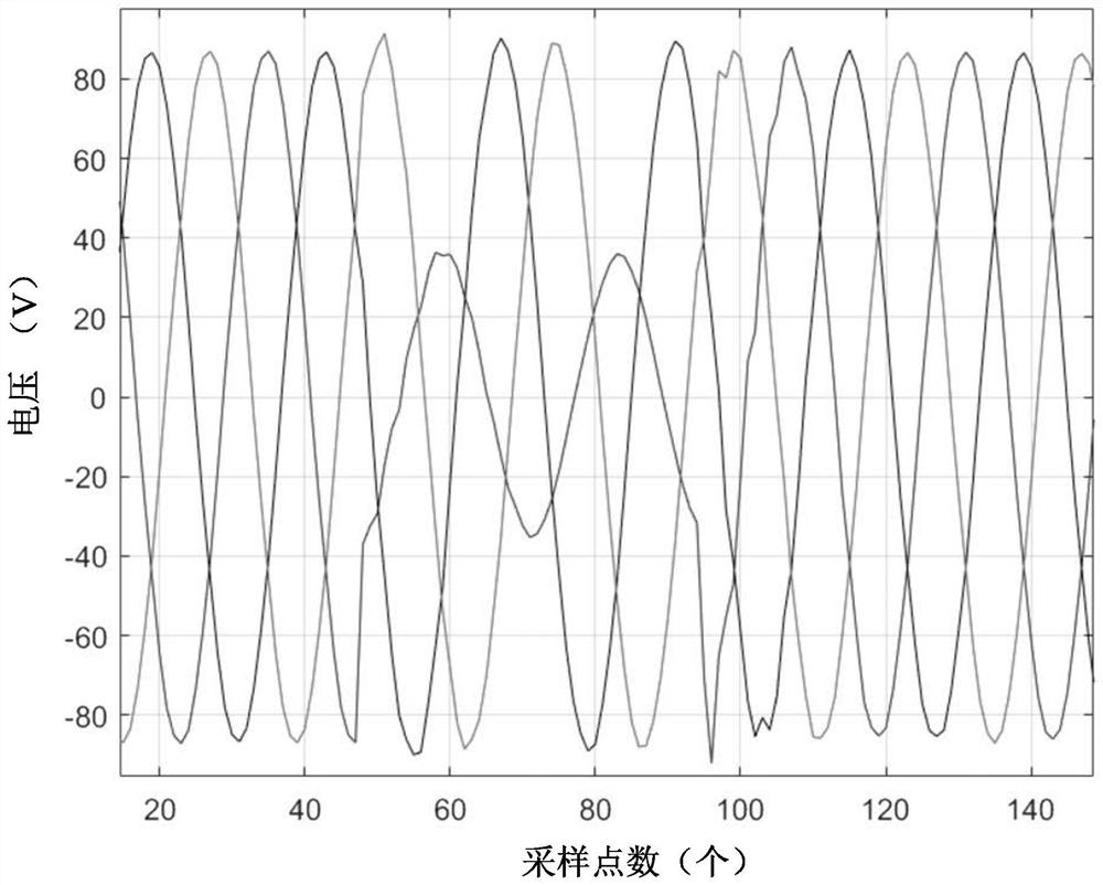
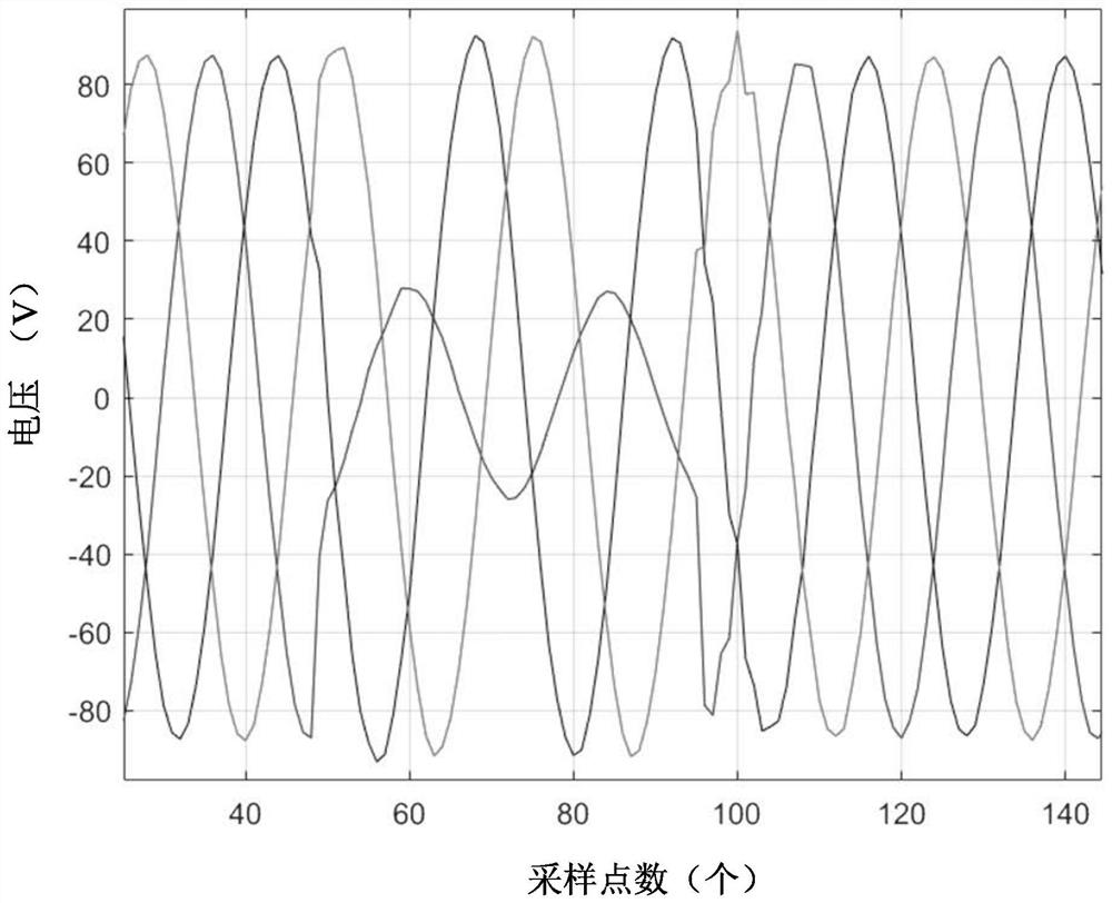
[0041] S1: Obtain the transient voltage and current at both ends of the first fault line when a fault occurs, for example, obtain the wave recording data of the substation at both ends of the fault line, which records the transient voltage at both ends of the first fault line when the fault occurs current. figure 1 shows the voltage recording data u at one end of the first fault line M (t), figure 2 shows the voltage recording data u at the other end of the first fault line N (t). Based on the distributed parameter model, the transient voltage and current distribution on the fault line is calculated.
[0042] S2: Determine the search step size, and generate multiple fault points to be determined on the fault line.
[0043]S3: Based on the instantaneous phase consistency of the transient voltage and current on the...
example 2
[0048] In this example, the method for judging the cause of the grid fault based on the calculation of the transition resistance includes the following steps:
[0049] S1: Obtain the voltage recording data at both ends of the second fault line when the fault occurs, such as Figure 4 and Figure 5 shown. in, Figure 4 shows the voltage recording data at one end of the second fault line, Figure 5 The voltage recording data at the other end of the second fault line is shown.
[0050] S2: Determine the change trend of the transition resistance according to the wave recording data, Figure 6 The change trend of the transition resistance of the second fault line is shown.
[0051] S3: Determine the cause of the grid fault. If the change trend of the transition resistance is a rapid decrease in resistance, the cause of the fault is external force damage. If the change trend of the transition resistance is no obvious mutation, the cause of the fault is lightning.
[0052] S4: ...
example 3
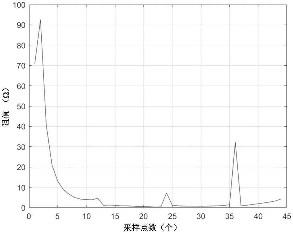
[0056] In this example, Figure 7 It shows the transition resistance values of 36 sampling points of the third fault line when the fault occurs when the frequency is 1200 Hz. ignoring Figure 7 post-judgment of spike interference in Figure 7 The change trend of the transition resistance is shown. At the 0th sampling point, the resistance value of the transition resistance is about 180Ω; at the 6th sampling point, the resistance value of the transition resistance is about 90Ω; at the 12th sampling point, the resistance value of the transition resistance is about 30Ω; at the 18th sampling point At the 24th sampling point, the transition resistance is about 20Ω; at the 30th sampling point, the transition resistance is about 15Ω; at the 36th sampling point, the transition resistance is The resistance is about 15Ω. Then, in the first 0.01s after the fault occurs, the resistance value change rate of the transition resistance is 15000Ω / s, and the drop rate is greater than 500Ω...
PUM
 Abstract
Description
Claims
Application Information