Geological inversion method based on land and underwater direct current combined measurement

A direct current and terrestrial technology, applied in geophysical surveying, radio wave measuring systems, measuring devices, etc., can solve problems such as technical incompleteness, and achieve the effect of eliminating the impact

Active Publication Date: 2022-05-13
CHENGDU UNIVERSITY OF TECHNOLOGY
View PDF6 Cites 0 Cited by
  • Summary
  • Abstract
  • Description
  • Claims
  • Application Information

AI Technical Summary

Problems solved by technology

However, looking at the current progress, there is little research on the joint measurement and inversion of land and underwater direct current, and the technology is not yet complete.

Method used


Image

  • Geological inversion method based on land and underwater direct current combined measurement
  • Geological inversion method based on land and underwater direct current combined measurement
  • Geological inversion method based on land and underwater direct current combined measurement

Examples


Embodiment 1

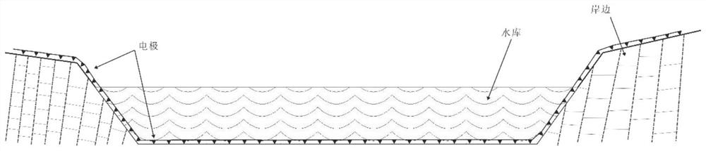
[0069] Such as figure 1 As shown, in order to achieve the transition from the shore to the deep water gradually, so as to achieve the purpose of effectively controlling the relevant geological bodies below and around the water body, the present invention first requires that the electrode array be gradually arranged from the land to the water, and then arranged on the land again;

[0070] In order to reduce the impact of the water body on the inversion, the present invention requires the use of sonar devices to control the three-dimensional model of the water body and bottom topography in the current entire work area before the design of the observation system and inversion, and to collect water samples at different depths and points , to analyze the three-dimensional distribution of the resistivity of the water body, and whether there is an obvious macroscopic stratification of the resistivity.

[0071] according to figure 1 For the land and underwater resistivity layout show...

Embodiment 2

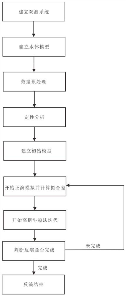
[0078] Such as figure 2 As shown, the present invention discloses a geological inversion method based on joint measurement of land and underwater direct current, comprising the following steps:

[0079] 1. Land-underwater-land electrode arrangement

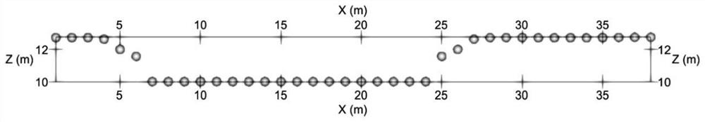
[0080] Such as image 3 As shown, the vertical Z in the figure represents the elevation, and the horizontal X represents the horizontal distance. It is necessary to arrange the electrodes from the land to the underwater, and then to the land. The underwater electrodes are in contact with the bottom of the water, and the water depth is about 1.5 meters. The electrodes pass through the water from the left bank to the right bank.

[0081] 2. Establish a water body model

[0082] Such as Figure 4 As shown, according to the sonar detection results, the spatial distribution of the water body is established; the actual water surface and the elevation of the water body are obtained according to the GPS measurement; according to the ...


PUM


Abstract

The invention discloses a geological inversion method based on land and underwater direct current combined measurement, and the method comprises the following steps: S1, arranging electrodes in a target region, the target region comprises a water area, the two sides of the water area are land, and the electrodes are gradually arranged from the land on one side to the bottom of the water area until the electrodes are arranged on the land on the other side; s2, determining spatial distribution of a water body in the water area by adopting a sonar detection device, collecting water samples at different depths and different point positions of the water area for analysis, determining a resistivity spatial distribution structure of the water body, and establishing a three-dimensional model of topographic relief of the water body and the water bottom in the water area; on the basis of direct-current combined measurement, multiple technical key points are designed from the actual angle, and the method comprises the steps that a progressive measurement method from land to water is adopted, and the geological condition from the shoreside to a deep water area is effectively controlled; the influence of flowing water on electrode disturbance is eliminated; and establishing a reservoir model, and eliminating the influence of a water body on underground medium inversion.

Description

technical field [0001] The invention belongs to the technical field of land and underwater direct current detection, and in particular relates to a geological inversion method based on joint measurement of land and underwater direct current. Background technique [0002] So far, the forward and inversion methods and theories of direct current are relatively mature, and the ground direct current method is widely used and relatively stable. However, looking at the current progress, there is little research on the joint measurement and retrieval of land and underwater direct current, and the technology is not complete. The safety detection of reservoirs and hydropower project dams is limited by the limitations of conventional methods and urgently needs to be broken through. It is particularly important to carry out research on land and underwater direct current joint measurement and inversion methods considering the hydrodynamic environment. Contents of the invention [0003...

Claims


Application Information

Patent Timeline
Patent Type & Authority Applications(China)
IPC IPC(8): G01V3/04G01V3/38
CPCG01V3/04G01V3/38Y02A90/30
Inventor 王堃鹏王向鹏焦永春李棂泽纪伟
Owner CHENGDU UNIVERSITY OF TECHNOLOGY
Why Eureka
Try Eureka