Contour lower section design method and tire

A cross-section design and contour technology, applied in special tires, tire parts, design optimization/simulation, etc., can solve the problem of not fully meeting the performance and safety requirements of run-flat safety tires, and achieve the goal of reducing roundness. The effect of approaching, preventing rollover, and increasing flexibility

Pending Publication Date: 2022-05-13
QINGDAO DOUBLESTAR TIRE IND CO LTD
View PDF0 Cites 2 Cited by
  • Summary
  • Abstract
  • Description
  • Claims
  • Application Information

AI Technical Summary

Problems solved by technology

The design idea of ​​using the general tire profile cannot fully meet the performance and safety requirements of the run-flat safety

Method used


Image

  • Contour lower section design method and tire
  • Contour lower section design method and tire

Examples


Example Embodiment

[0039] Example 1

[0040] Step 1, establish an initial tire profile model according to the selected tire model 225 / 55R17;

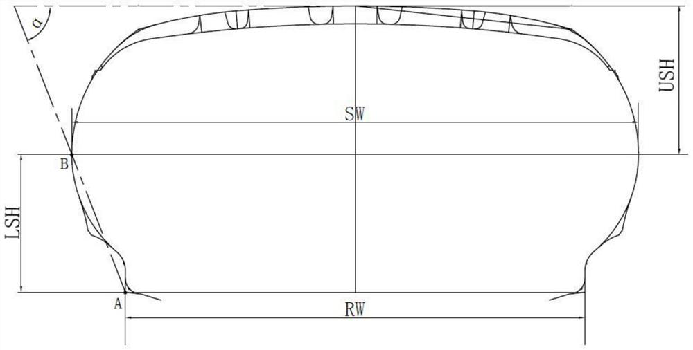
[0041]Step 2. According to the outer diameter D of the tire, the diameter of the rim and the diameter d, the section height SH=1 / 2(D-d) is obtained, and the lower section height LSH and the upper section height USH of the profile are adjusted to make LSH / USH=1.05;

[0042] Step 3. Adjust the contour width RW to 191mm;

[0043] Step 4. Adjust the profile section width SW to 238mm;

[0044] Step 5. Construct the functional relationship of the contour parameters according to the test data in steps 2 to 4, and verify by the formula tanα=2LSH / (SW-RW), and the calculated value of α is 68.8°.

Example Embodiment

[0045] Example 2

[0046] Step 1, establish an initial tire profile model according to the selected tire model 215 / 65R16;

[0047] Step 2. According to the tire outer diameter D, rim diameter and diameter d, obtain the section height SH=1 / 2(D-d), adjust the profile lower section height LSH and upper section height USH, so that LSH / USH=1.08;

[0048] Step 3. Adjust the contour width RW to 185mm;

[0049] Step 4, adjust the profile section width SW to 226mm;

[0050] Step 5. Construct the functional relationship of the contour parameters according to the test data in steps 2 to 4, and verify by the formula tanα=2LSH / (SW-RW), and the calculated value of α is 74.1°.

Example

[0061] Table 1 embodiment 2 and comparative example 2 driving force factor and braking force factor test table

[0062] Test items Example 2 Comparative example 2 Driving radial force / N 3445.6 3489.7 Maximum longitudinal force when driving / N 4976.2 4876.4 driving force factor 1.44 1.40 Braking radial force / N 3449.9 3492.6 Maximum longitudinal force during braking / N -4195.3 -4176.3 braking force factor 1.22 1.20

[0063] Through the test comparison of Example 2 and Comparative Example 2, it can be seen that the test result of Example 2 is better than that of Comparative Example 2. It can be seen that the design of the over-large width RW is not good for the traction performance, and it will also increase The pressure on the bead causes the bead to break and cause damage to the rim.


PUM


Abstract

The invention provides a profile lower section design method, belongs to the field of tire profile design, and can solve the technical problems that the overturning torque of an anti-explosion tire suitable for a common profile is increased, and the steady-state performance of the tire is poor. According to the technical scheme, the method comprises the following steps that 1, an initial tire contour model is established according to a selected tire model; 2, according to the tire outer diameter D and the rim sum diameter d, the section height SH = 1/2 (D-d) is obtained, the parameters of the contour lower section height LSH and the contour upper section height USH are adjusted, and LSH is made to be larger than USH; 3, the contour fitting width RW is adjusted according to the standard rim width Rm; 4, according to the relation between the contour fitting width RW and the contour section width SW, the contour section width SW is adjusted; and step 5, constructing a function relationship of contour parameters according to the test data in the steps 2-4, and verifying through a formula until a contour model meeting the requirements is obtained. The method can be applied to the contour of the self-supporting tire of the full-series passenger car.

Description

technical field [0001] The invention belongs to the field of tire contour design, in particular to a method for designing a section under contour and a tire. Background technique [0002] With the rapid development of science and technology, the improvement of highway construction and the improvement of living standards, people put forward higher requirements for the safety performance and comfort performance of automobiles at high speeds. As the only key part of the car in contact with the road during driving, the basic function of the tire is to support the weight of the vehicle, transmit the driving and braking torque, and ensure the steering stability. Its safety performance plays a vital role in the safety performance of the car. [0003] In the existing self-supporting run-flat tires, a strong and hard support rubber is usually added to the sidewall to ensure its zero-pressure durability. The sidewall of the tire supports the vehicle to continue running, but when driv...

Claims


Application Information

Patent Timeline
IPC IPC(8): G06F30/20B60C3/00G06F119/14
CPCG06F30/20B60C3/00G06F2119/14
Inventor 徐伟王君魏颖刘继发张琳刘杰苏明韩磊刘俊杰张峰王宏霞王振孙桂芹马洁韩俊宇孙超
Owner QINGDAO DOUBLESTAR TIRE IND CO LTD
Why Eureka
Try Eureka