Electric power wire harness thermal shrinkage operation auxiliary device

An auxiliary device and heat shrinking technology, applied in the manufacture of wire harnesses, heat treatment equipment, circuits, etc., can solve the problems of high labor intensity, differences in heat shrinking standards and reliability, and low work efficiency, so as to improve labor efficiency, Improve heat shrinking effect and avoid cumbersome effects

Active Publication Date: 2022-05-13
国网山东省电力公司沂水县供电公司
View PDF5 Cites 0 Cited by
  • Summary
  • Abstract
  • Description
  • Claims
  • Application Information

AI Technical Summary

Problems solved by technology

[0003] Wire harness heat shrinking is often encountered in electrical work. The traditional heat shrinking process is all manual. People put the heat shrinkable tube on the wire harness, then push the heat shrinkable tube to the outside of the solder joint, and then hold the heat gun and For wiring harness, heat shrinks the heat-shrinkable tube, which has high labor intensity and low work efficiency
And due to different personal experience and habits, there are great differences in the standard and reliability of heat shrink

Method used


Image

  • Electric power wire harness thermal shrinkage operation auxiliary device
  • Electric power wire harness thermal shrinkage operation auxiliary device
  • Electric power wire harness thermal shrinkage operation auxiliary device

Examples


Embodiment Construction

[0027] The application will be further described below in conjunction with the accompanying drawings and embodiments.

[0028] It should be noted that the terminology used herein is only for describing specific embodiments, and is not intended to limit the exemplary embodiments according to the present disclosure. As used herein, unless the context clearly dictates otherwise, the singular is intended to include the plural, and it should also be understood that when the terms "comprising" and / or "comprising" are used in this specification, they mean There are features, steps, operations, means, components and / or combinations thereof.

[0029] In this disclosure, terms such as "upper", "lower", "left", "right", "front", "rear", "vertical", "horizontal", "side", "bottom" etc. refer to The orientation or positional relationship is based on the orientation or positional relationship shown in the drawings, and is only a relative term determined for the convenience of describing the...


PUM


Abstract

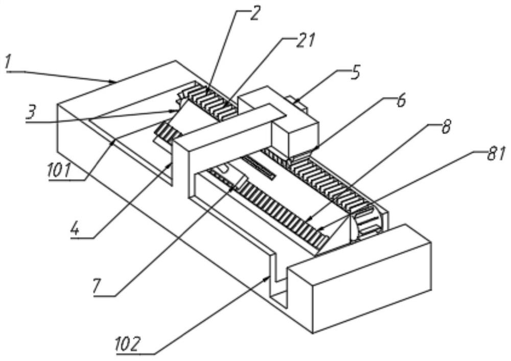
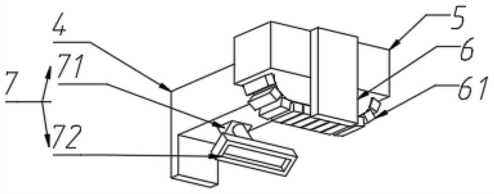
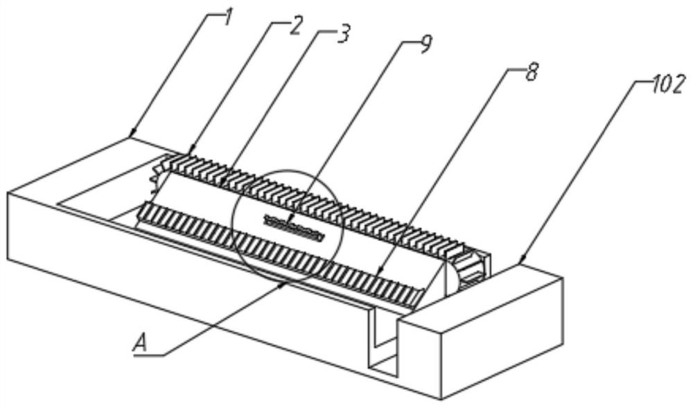
The invention provides an electric power wire harness thermal shrinkage operation auxiliary device which comprises a base and a support fixedly arranged above the base, a thermal shrinkage bin is formed in the center of the top of the base, a first conveying belt is arranged on one side of the thermal shrinkage bin, and a synchronous belt is arranged above the middle of the first conveying belt; the first conveying belt and the synchronous belt are provided with a partition plate and a pressing block which are matched with each other respectively, a slope block is tightly attached to one side of the first conveying belt, a wire harness push-pull mechanism is arranged on the slope block, a telescopic mechanism opposite to the slope of the slope block is arranged above the slope block, and a thermal shrinkage device is arranged on an output shaft of the telescopic mechanism. The telescopic mechanism and the synchronous belt are connected to the support, and a storage groove is transversely formed in the front side of the thermal shrinkage bin relative to the tail end of the first conveying belt. According to the invention, the heat shrink tubes are automatically aligned and thermally shrunk in batches, so that the labor efficiency is improved.

Description

technical field [0001] The application relates to the technical field of heat shrinking of cables, in particular to an auxiliary device for heat shrinking of electric wire harnesses. Background technique [0002] The statements in this section merely provide background technical information relevant to this application and do not necessarily constitute prior art. [0003] Wire harness heat shrinking is often encountered in electrical work. The traditional heat shrinking process is manual operation. People put the heat shrinkable tube on the wire harness, then push the heat shrinkable tube to the outside of the solder joint, and then hold the heat gun and For the wire harness, heat shrinks the heat-shrinkable tube, which has high labor intensity and low work efficiency. Moreover, due to differences in personal experience and habits, there are also great differences in the standards and reliability of heat shrinkage. Contents of the invention [0004] In order to solve the...

Claims


Application Information

Patent Timeline
Patent Type & Authority Applications(China)
IPC IPC(8): H01B13/012H01B13/00
CPCH01B13/01263H01B13/01209H01B13/0016Y02W30/82
Inventor 李伟李静鹏张峰田磊鲁亚楠李飞李轶群戚斌梁镓瑞张瑗申张广珍赵清华王会凯闫鹏飞张军吕杨姚贵栋高萍
Owner 国网山东省电力公司沂水县供电公司
Why Eureka
Try Eureka