
Charging module fault communication system and method

A charging module and communication system technology, applied in the field of communication, can solve the problem of low efficiency of fault handling of charging modules, and achieve the effect of improving fault handling capability and rapid protection response.

Pending Publication Date: 2022-05-13
ZTEV
View PDF0 Cites 0 Cited by
  • Summary
  • Abstract
  • Description
  • Claims
  • Application Information

AI Technical Summary

Problems solved by technology

[0005] The main purpose of the present invention is to provide a charging module failure communication system and method, aiming to solve the technical problem of low efficiency of charging module failure handling in the prior art

Method used


Image

  • Charging module fault communication system and method
  • Charging module fault communication system and method
  • Charging module fault communication system and method

Examples


Embodiment Construction

[0048] It should be understood that the specific embodiments described here are only used to explain the present invention, not to limit the present invention.

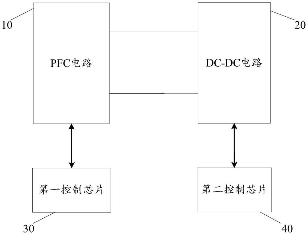
[0049] refer to figure 1 , figure 1 It is a structural diagram of the first embodiment of the charging module failure communication system of the present invention.

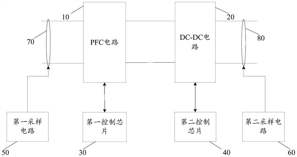
[0050] like figure 1 As shown, the charging module failure communication system of the present invention includes: a PFC circuit 10, a DC-DC circuit 20, a first control chip 30 and a second control chip 40, the PFC circuit 10 is connected to the first control chip 30, and the The DC-DC circuit 20 is connected to the second control chip 40, and the PFC circuit 10 is connected to the DC-DC circuit 20; the PFC circuit 10 is used to control the current waveform input by the charging module so that the The current waveform is synchronized with the voltage waveform input by the charging module; the DC-DC circuit 20 is used to convert the voltage input by th...


PUM


Abstract

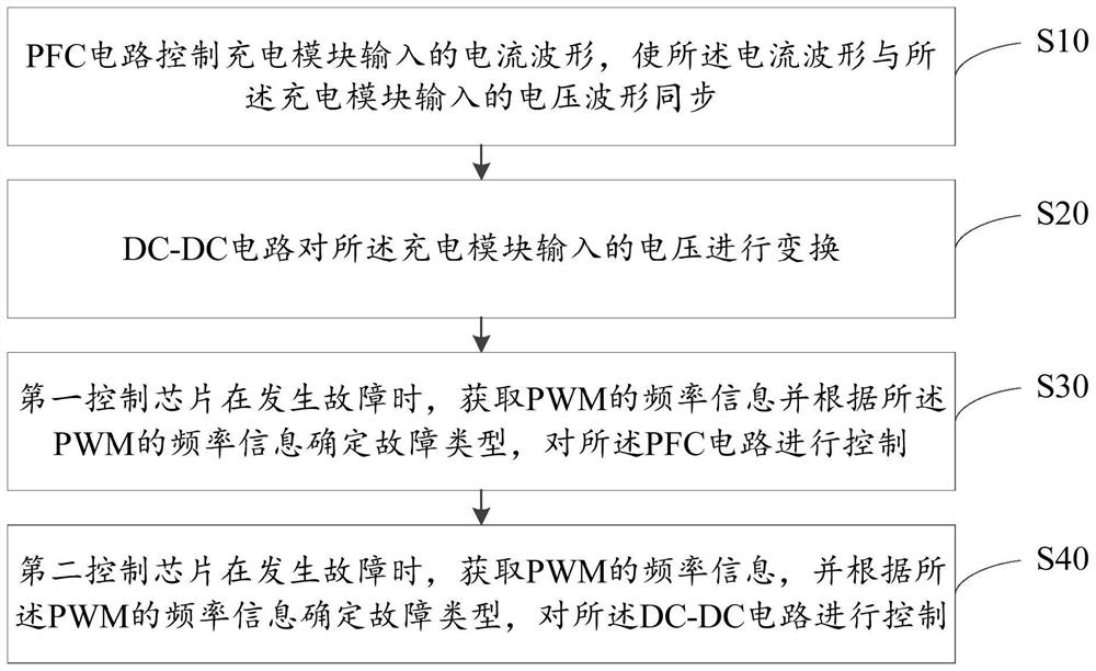
The invention discloses a charging module fault communication system and method, and belongs to the technical field of communication. A PFC circuit, a DC-DC circuit, a first control chip and a second control chip are arranged in a charging module fault communication system, and the PFC circuit is used for controlling a current waveform input by a charging module, so that the current waveform is synchronized with a voltage waveform input by the charging module; the DC-DC circuit is used for converting the voltage input by the charging module; the first control chip and the second control chip are used for acquiring PWM frequency information and performing corresponding circuit control when a certain level of circuit of the charging module fails or input and output emergencies occur, so that information intercommunication between power conversion links can be quickly realized, quick protection response is performed on the circuit of the charging module, and the service life of the charging module is prolonged. And the fault processing capability of the charging module is improved.

Description

technical field [0001] The invention relates to the field of communication technology, in particular to a charging module failure communication system and method. Background technique [0002] The charging module contains two power conversion links. The first link is the front-stage AC-DC link, which is generally realized by PFC; the second link is the rear-stage DC-DC link, which is generally realized by LLC circuit or full-bridge shifting equalization technology. , between the two power conversion links, it is necessary to transmit signals such as control quantity and protection quantity. When a circuit of a certain stage of the charging module fails or an emergency occurs in the input and output, a fast communication method is needed to realize the two power conversion links. The information exchange among them is to realize the fast protection response of the power conversion link. [0003] The existing communication method is realized by I / O port communication method t...

Claims


Application Information

Patent Timeline
IPC IPC(8): H02M1/42H02M3/00H02J7/00H02J7/02H02H7/12H02H1/00
CPCH02M1/4208H02M3/00H02J7/00036H02J7/02H02H7/12H02H7/1213H02H1/0007H02J2207/20Y02B70/10
Inventor 邓斌胡超江翔
Owner ZTEV
Learn More