
Movable groove type drying structure

A mobile, drying mechanism technology, applied in drying, drying machine, drying solid materials, etc., can solve the problems of single air outlet, single air outlet and direction, and poor controllability, so as to improve the drying and blowing effect Effect

Active Publication Date: 2022-05-17
JIANGSU ASIA ELECTRONICS TECH CO LTD
View PDF27 Cites 0 Cited by
  • Summary
  • Abstract
  • Description
  • Claims
  • Application Information

AI Technical Summary

Problems solved by technology

[0002] With the development of the solar photovoltaic industry, the development trend of crystalline silicon cells is low cost, high efficiency, and large output. The preparation of crystalline silicon cells needs to go through various process tanks, and drying tanks are one of them. Among the existing equipment , the blowing direction of the drying tank is fixed, resulting in a single way of blowing air, poor controllability, and low drying efficiency, and the existing drying devices have a single air outlet and direction, which cannot be adjusted, and some batteries with special structures require The drying effect can only be achieved by the wind force of greater flow rate and different angles of drying and blowing

Method used


Image

  • Movable groove type drying structure
  • Movable groove type drying structure
  • Movable groove type drying structure

Examples


Embodiment 1

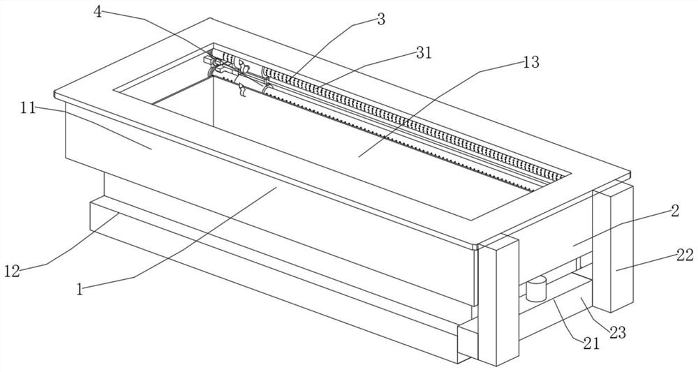
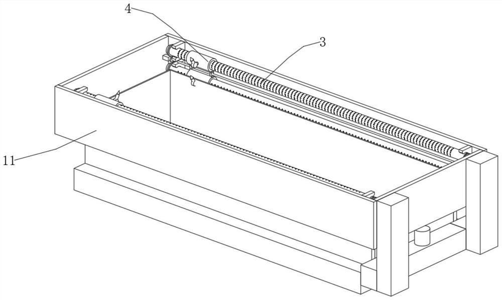
[0040] Such as Figure 1-Figure 7 As shown, a mobile trough drying structure includes a drying mechanism 1 and a circulation mechanism 2. The circulation mechanism 2 is installed outside the drying mechanism 1, and also includes an air duct mechanism 3 for providing drying and blowing and for realizing The mobile drying and blowing mechanism 4 for mobile drying and the opening and closing mechanism 5 for cooperating with the air duct mechanism 3 and the mobile drying and blowing mechanism 4;

[0041] The drying mechanism 1 includes a drying tank 11, a base 12, and a hollow base plate 13. The base 12 is installed at the lower end of the drying tank 11, and the hollow base plate 13 is arranged at the inner bottom of the drying tank 11;

[0042] The circulation mechanism 2 includes an air pump 21, an air intake pipe 22, and a recovery pipe 23. The air pump 21 is installed outside the drying tank 11. An air intake pipe 22 is installed on the upper end of the air pump 21, and a rec...


PUM


Abstract

The invention discloses a movable groove type drying structure which comprises a drying mechanism and a circulating mechanism, and the circulating mechanism is installed outside the drying mechanism. The air pipe mechanism is used for providing drying and blowing, the movable drying and blowing mechanism is used for achieving movable drying and blowing, and the opening and closing mechanism is used for being matched with the air pipe mechanism and the movable drying and blowing mechanism. Transverse moving drying and blowing are achieved through the movable drying and blowing mechanism, meanwhile, no new pipeline needs to be arranged, large air flow can be provided for the blowing nozzle only by collecting air of the air blowing pipe, and therefore the drying and blowing effect is improved, through the opening and closing mechanism, the position of the movable hollow cylinder can be adjusted under the condition of a single motor, and the drying and blowing efficiency is improved. And meanwhile, the drying and blowing angle of the air blowing pipe can be quickly adjusted when the drying and blowing angle needs to be adjusted.

Description

technical field [0001] The invention relates to the field of drying equipment, in particular to a mobile trough drying structure. Background technique [0002] With the development of the solar photovoltaic industry, the development trend of crystalline silicon cells is low cost, high efficiency, and large output. The preparation of crystalline silicon cells needs to go through various process tanks, and drying tanks are one of them. Among the existing equipment , the blowing direction of the drying tank is fixed, resulting in a single way of blowing air, poor controllability, and low drying efficiency, and the existing drying devices have a single air outlet and direction, which cannot be adjusted, and some batteries with special structures require The wind with a higher flow rate and different angles of drying can have a drying effect. Contents of the invention [0003] The object of the present invention is to provide a mobile trough drying structure in order to solve ...

Claims


Application Information

Patent Timeline
Patent Type & Authority Applications(China)
IPC IPC(8): F26B9/06F26B21/00F26B21/04F26B25/02H01L31/18
CPCF26B9/066F26B21/004F26B21/04F26B25/02H01L31/18Y02P70/10
Inventor 钱诚童建田晓东
Owner JIANGSU ASIA ELECTRONICS TECH CO LTD
Learn More