Test unit for improving WAT test precision and test method thereof

A test unit and test accuracy technology, applied in the direction of single semiconductor device test, measurement power, measurement device, etc., can solve problems such as insufficient test accuracy of machine or pin card, and achieve the effect of convenient and concise test process and reduced test cost.

Inactive Publication Date: 2022-05-17
GUANGZHOU CANSEMI TECH INC
View PDF9 Cites 1 Cited by
  • Summary
  • Abstract
  • Description
  • Claims
  • Application Information

AI Technical Summary

Problems solved by technology

[0005] In view of the above-mentioned shortcoming of the prior art, the purpose of the present invention is to provide a kind of test unit and test method thereof that improves WAT test accuracy, for while satisfying and can use existing test hardware condition, avoid prior art Insufficient test accuracy of the middle machine or needle card

Method used


Image

  • Test unit for improving WAT test precision and test method thereof
  • Test unit for improving WAT test precision and test method thereof
  • Test unit for improving WAT test precision and test method thereof

Examples


Embodiment 1

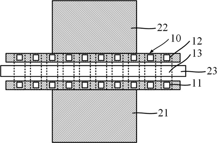
[0034] Such as image 3 As shown, the present embodiment provides a kind of testing unit that improves WAT testing precision, and the testing unit that described improving WAT testing precision comprises:

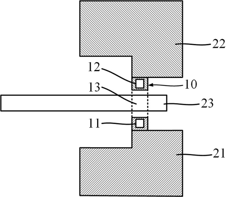
[0035] The MOS transistor area includes N MOS transistors 10 with the same feature size, N≥2, and the MOS transistor 10 includes a source 11, a drain 12, a gate 13 and a substrate;

[0036] a metal region, located above the MOS transistor region, the metal region includes a source metal region 21, a drain metal region 22, a gate metal region 23 and a substrate metal region;

[0037] interconnecting metal lines, for connecting the source 11 of the MOS transistor 10 to the source metal region 21, the drain 12 to the drain metal region 22, the gate 13 to the The gate metal region 23 is connected, and the substrate is connected to the substrate metal region, so that N MOS transistors 10 are connected in parallel. The test principle of the test unit of described improving WAT ...

Embodiment 2

[0046] The present embodiment provides a kind of test method of the test unit that improves WAT test accuracy, the test method of the test unit that improves WAT test accuracy can use the test unit that improves WAT test accuracy described in embodiment one, described improves WAT test The test method of the test unit of precision comprises the following steps:

[0047] Such as Figure 3 to Figure 4 As shown, step S1 is firstly performed to provide the test unit for improving the test accuracy of WAT.

[0048] Such as Figure 3 to Figure 4 Shown, then carry out step S2, the test unit that described improving WAT test accuracy is tested, obtain the leakage current total value I of described test unit all .

[0049] It should be noted here that the test hardware involved in this implementation, such as the test machine and the test needle card, is a hardware device in the prior art, which can directly measure the leakage current total value I of the test unit. all . The num...


PUM


Abstract

The invention provides a test unit for improving WAT test precision and a test method thereof, and the test unit for improving WAT test precision comprises an MOS transistor region which comprises N MOS transistors with the same feature size; the metal region is positioned above the MOS transistor region; and the interconnection metal wire is used for connecting the MOS transistors with the metal region, so that the N MOS transistors are connected in parallel. Under the condition that existing testing hardware is not changed, the problem that precision is insufficient when a testing machine and a needle card test the leakage current of the MOS transistor can be effectively solved, so that the leakage current of the MOS transistor can be accurately and efficiently tested; the testing process is convenient and simple, the testing cost can be reduced, and application and popularization of the method are facilitated; according to the invention, a small-size MOS transistor is tested, so that the performance of the MOS transistor can be known, and a solution is provided in subsequent chip design, so that chip integration is facilitated.

Description

technical field [0001] The invention relates to the field of semiconductor device preparation technology, in particular to a test unit and a test method for improving WAT test accuracy. Background technique [0002] Semiconductor technology In the design of integrated circuits or the development of process technology platforms, it is usually necessary to use a variety of leakage test structures to reflect whether the circuit design and process capabilities of semiconductor devices are normal. Different leakage test structures can reflect different device characteristics. The characteristics improve circuit design or process in semiconductor devices. Transistors are commonly used devices in semiconductor integrated chips. At present, for low-power integrated chips, the leakage current of transistors has become a crucial parameter, and the transistor leakage current directly affects the static power consumption of low-power integrated chips. As the integration level of the i...

Claims


Application Information

Patent Timeline
Patent Type & Authority Applications(China)
IPC IPC(8): G01R31/26
CPCG01R31/2639
Inventor 赖福东刘翔
Owner GUANGZHOU CANSEMI TECH INC
Why Eureka
Try Eureka