
Automatic adjustment display screen

An automatic adjustment and display screen technology, applied in the field of display screens, can solve the problems of large space occupation area, fixed display screen structure, and inability to effectively protect the display screen, so as to ensure normal use, reduce space occupation area, and improve heat dissipation efficiency. Effect

Pending Publication Date: 2022-05-17
深圳市六道文化传播有限公司
View PDF0 Cites 0 Cited by
  • Summary
  • Abstract
  • Description
  • Claims
  • Application Information

AI Technical Summary

Problems solved by technology

[0004] The self-adjusting display screen proposed by this application solves the problem that the existing display screen structure is fixed and cannot be folded and contracted, resulting in a large space occupation area and the problem that the display screen cannot be effectively protected when it is idle

Method used


Image

  • Automatic adjustment display screen
  • Automatic adjustment display screen
  • Automatic adjustment display screen

Examples


Embodiment 1

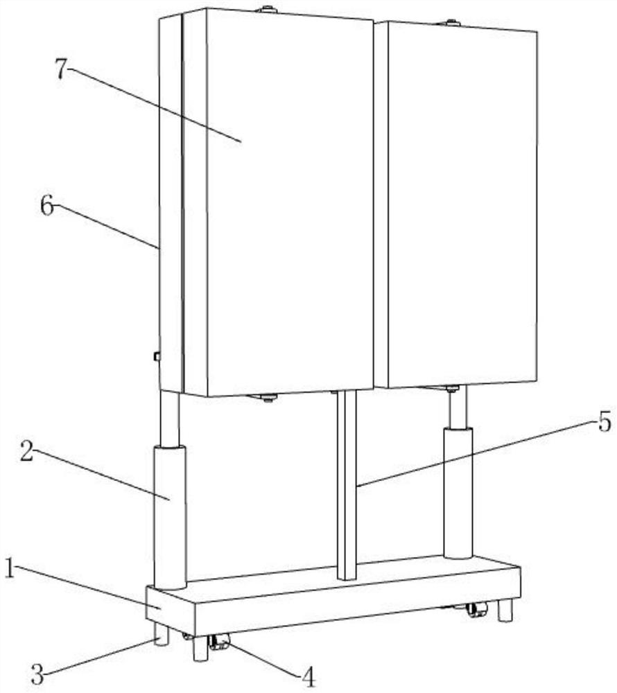
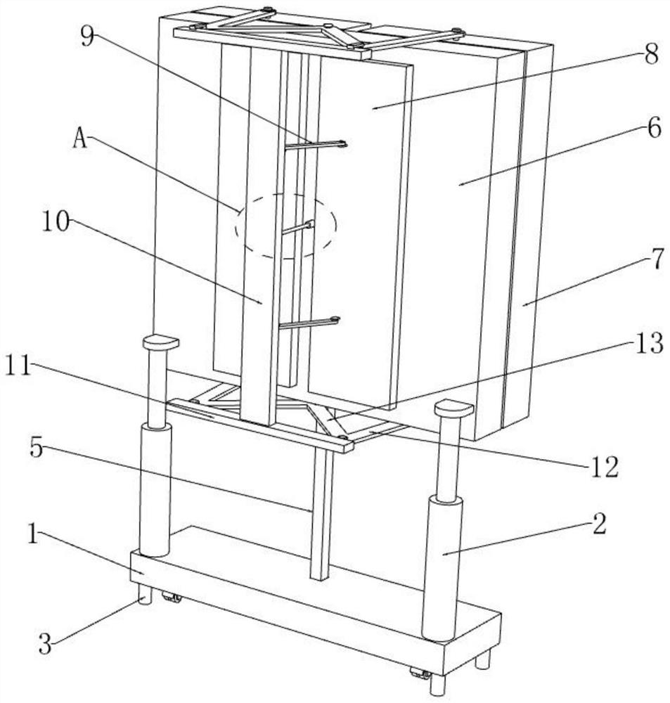
[0032] refer to figure 1 and figure 2 , an automatic adjustment display screen, comprising a bottom plate 1, the four corners of the bottom end of the bottom plate 1 are fixedly equipped with support legs 3, the bottom ends of the support legs 3 are fixedly installed with anti-skid pads, and the top of the bottom plate 1 is fixedly installed with two symmetrically distributed The first electric telescopic rods 2, the tops of the two first electric telescopic rods 2 are fixedly connected with the first display screen 6, the back of the first display screen 6 is provided with a plurality of cooling holes distributed in matrix, the first display screen The two sides of 6 are rotationally installed with the second display screen 7 that is symmetrically distributed.

[0033] refer to figure 1 and Figure 4 , the bottom end of the first display screen 6 is fixedly connected with the connecting rod 5, the bottom end of the bottom plate 1 is provided with a storage groove 15, the ...

Embodiment 2

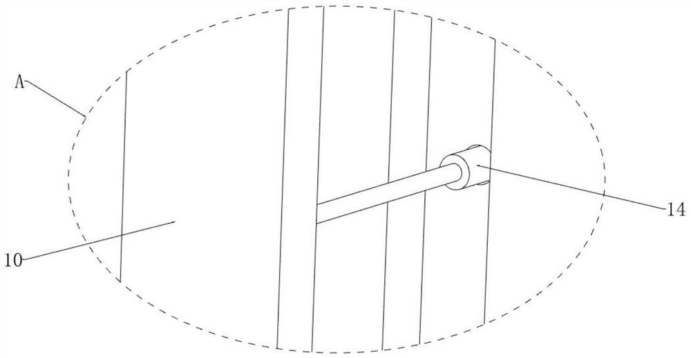
[0038] refer to figure 2 and Figure 4, the back of the first display screen 6 is slidingly installed with two symmetrically distributed dust-proof panels 8, and a push rod 9 is hingedly installed between the dust-proof panels 8 and the risers 10, and two groups of The chute is symmetrically distributed, and the side of the dustproof plate 8 close to the first display screen 6 is fixedly connected with two symmetrically distributed sliders, the sliders are slidably installed inside the chute, and the sliding of the slider inside the chute can be To ensure the stability of the dust-proof plate 8 when it moves, the side of the dust-proof plate 8 close to the first display screen 6 is equipped with evenly distributed dust-removing hair brushes. Perform simple cleaning to avoid clogging of cooling holes.

[0039] When the first display screen 6 and the second display screen 7 are unfolded and in use, the riser 10 will push the push rod 9, and the push rod 9 will push the dustpr...


PUM


Abstract

The invention discloses an automatic adjusting display screen, relates to the field of display screens, and provides the following scheme aiming at the problems that an existing display screen is fixed in structure and cannot be folded and contracted, so that the space occupied area is large, and the display screen cannot be effectively protected when the display screen is idle. Two symmetrically-distributed first electric telescopic rods are fixedly installed at the top end of the bottom plate, the top ends of the two first electric telescopic rods are jointly and fixedly connected with a first display screen, and a plurality of heat dissipation holes distributed in a matrix mode are formed in the back face of the first display screen. And second display screens which are symmetrically distributed are rotationally mounted on the two sides of the first display screen. According to the display screen, the space occupied area when the display screen is idle is reduced through folding of the display screen, effective anti-collision and dustproof protection is conducted on the display screen, when the display screen is unfolded for use, the heat dissipation holes are opened through unfolding of the dustproof plates, and the heat dissipation efficiency of the display screen in use is effectively improved.

Description

technical field [0001] The present application relates to the field of display screens, in particular to an automatic adjustment display screen. Background technique [0002] The display screen is composed of LED dot matrix. It displays text, pictures, animations, and videos by turning on and off the red, blue, yellow, white, and green lamp beads. The content can be changed at any time as long as you think of it. It is displayed on the display screen in the computer, and each part of the components is a display device with a modular structure, usually composed of a display module, a control system and a power supply system. [0003] Existing display screens are generally integrated, with a relatively fixed structure, which cannot be folded and contracted, resulting in a large space occupation area, and when the display screen is idle, the screen cannot be effectively protected, resulting in damage to the screen due to collisions Or stick a lot of dust, so in order to solve ...

Claims


Application Information

Patent Timeline
IPC IPC(8): G09F9/302G09F9/33H05K5/02H05K7/20B08B1/00
CPCG09F9/302G09F9/33H05K7/20954B08B1/12
Inventor 邓李威曾前云
Owner 深圳市六道文化传播有限公司
Learn More