
Intelligent street lamp aggregation gateway

A technology of smart street lights and aggregation network, applied in the direction of network connection, instruments, TV, etc., can solve the problems of increased use and maintenance costs, uncontrolled equipment, troublesome installation and maintenance personnel, etc., to simplify maintenance work, reduce risks, prevent Effects of router short circuits and damage to internal parts

Inactive Publication Date: 2022-05-17
HEFEI DAMING ENERGY SAVING TECH
View PDF0 Cites 0 Cited by
  • Summary
  • Abstract
  • Description
  • Claims
  • Application Information

AI Technical Summary

Problems solved by technology

[0005] The invention provides a smart street lamp aggregation gateway, which solves the problem that the method of connecting equipment to the Internet causes great trouble to the installation and maintenance personnel in the process of installation, wiring, and maintenance. In addition, the equipment is not controlled, and if a certain equipment has a problem, it must be contacted. On-site inspection and replacement will increase the cost of use and maintenance

Method used


Image

  • Intelligent street lamp aggregation gateway
  • Intelligent street lamp aggregation gateway
  • Intelligent street lamp aggregation gateway

Examples


no. 1 example

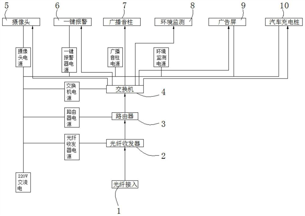
[0034] Please refer to figure 1 ,in, figure 1 A schematic structural diagram of the first embodiment of the smart street lamp aggregation gateway provided by the present invention. A smart street lamp aggregation gateway, comprising: optical fiber access 1;

[0035] An optical fiber transceiver 2, the optical fiber transceiver 2 is arranged on one side of the optical fiber access 1;

[0036] A router 3, the router 3 is arranged on one side of the optical fiber transceiver 2;

[0037] Switch 4, the switch 4 is arranged on one side of the router 3, the output of the switch 4 is respectively connected with a camera 5, a key alarm 6, a broadcast sound column 7, an environmental monitoring 8, an advertising screen 9 and a car Charging pile 10.

[0038] When the gateway is powered, the 220V AC power is connected to the fiber optic transceiver power supply, router power supply, switch power supply, camera power supply, one-button alarm power supply, broadcast sound column power s...

no. 2 example

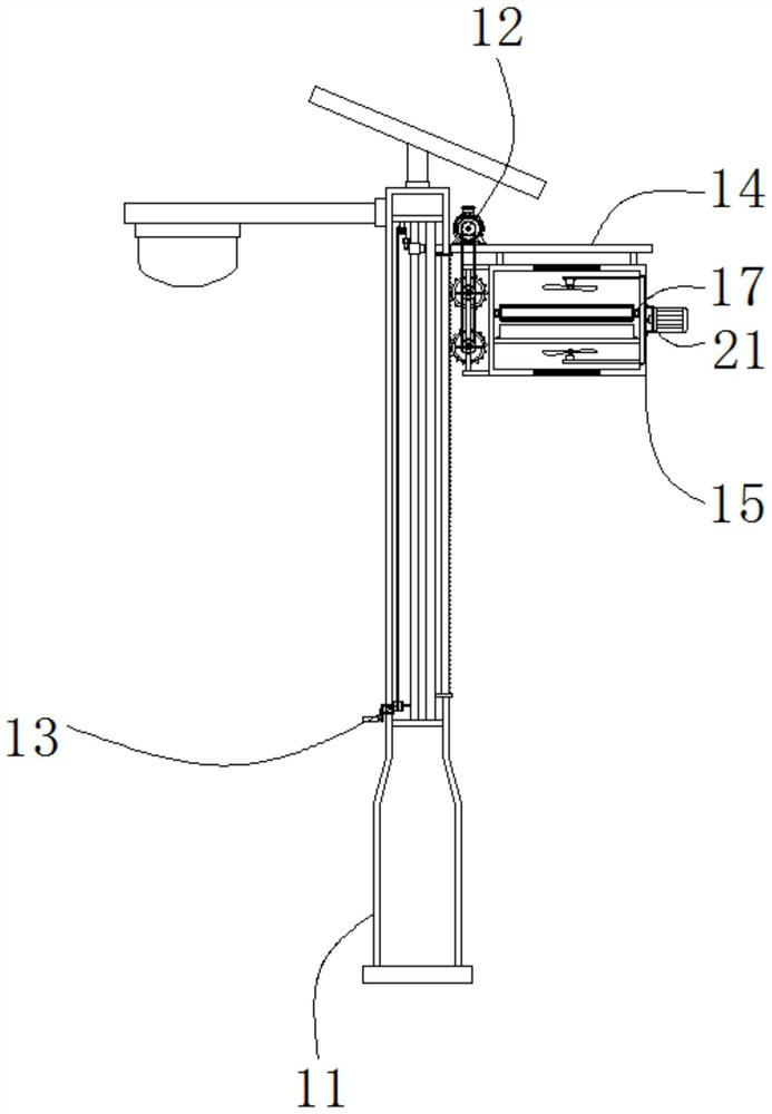
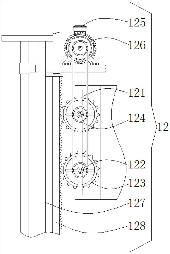
[0046] Please refer to figure 2 , image 3 , Figure 4 , Figure 5 , Figure 6 and Figure 7 , based on the smart street lamp aggregation gateway provided in the first embodiment of the present application, the second embodiment of the present application proposes another smart street lamp aggregation gateway. The second embodiment is only a preferred mode of the first embodiment, and the implementation of the second embodiment will not affect the independent implementation of the first embodiment.

[0047] Specifically, the difference between the smart street lamp aggregation gateway provided by the second embodiment of the present application is that it is a smart street lamp aggregation gateway, the smart street lamp aggregation gateway is set above the light pole 11, and the light pole 11 The interior of the lifting device 12 is provided with a lifting device 12, and the lifting device 12 includes a mounting frame 121. Both sides of the mounting frame 121 are provide...


PUM


Abstract

The invention provides an intelligent street lamp aggregation gateway. The intelligent street lamp aggregation gateway comprises optical fiber access; the optical fiber transceiver is arranged on one side of the optical fiber access; the router is arranged on one side of the optical fiber transceiver; the switch is arranged on one side of the router, and the output end of the switch is connected with a camera, a one-key alarm, a broadcast sound post, an environment monitor, an advertisement screen and an automobile charging pile. According to the intelligent street lamp aggregation gateway provided by the invention, equipment such as a router, a switch, a power supply, an optical fiber transceiver and the like required in an intelligent lamp pole is omitted, so that the field installation, wiring and maintenance work is greatly simplified, the management of each functional module is controllable, a user remotely masters the working state of each module, and the user experience is improved. And through cooperative use of the lifting device and the pulling device, the box body can be conveniently lifted, an operator can conveniently maintain and replace the router, and the risk of climbing maintenance can be reduced.

Description

technical field [0001] The invention relates to the field of street lamps, in particular to a smart street lamp aggregation gateway. Background technique [0002] Smart light poles, also known as multi-functional light poles, are an important part of new infrastructure and smart cities, as well as the carrier of various sensing devices in smart cities. [0003] At present, when the smart light pole is mounted with these devices, each device has an independent power supply, and then connected to the switch. The switch needs to be connected to the Internet and also needs to be connected to optical fiber transceivers, routers and other equipment. The method of connecting these devices to the Internet As a result, the installation and maintenance personnel are very troubled during the installation, wiring and maintenance process. In addition, the equipment is out of control. If a certain equipment has a problem, it must be checked and replaced on site, which increases the use an...

Claims


Application Information

Patent Timeline
Patent Type & Authority Applications(China)
IPC IPC(8): H04L12/66H04Q1/02H04N5/225H04R1/02G08B25/12F16M11/04F16M11/18F21V33/00H05K7/20
CPCH04L12/66H04Q1/02G08B25/12H04R1/025F21V33/00F21V33/0076H05K7/20136F16M11/046F16M11/18F21W2131/103H04N23/57Y02B20/72
Inventor 杜庆朋黎仁安陈利文
Owner HEFEI DAMING ENERGY SAVING TECH
Learn More