
Hydraulic coupler for continuously variable transmission

A technology of hydraulic coupling and semi-circular ring, which is applied in the direction of clutches, clutches, fluid clutches, etc., and can solve the problem that the torque cannot be multiplied

Pending Publication Date: 2022-05-17
沙达蓬·苏普里查科
View PDF0 Cites 0 Cited by
  • Summary
  • Abstract
  • Description
  • Claims
  • Application Information

AI Technical Summary

Problems solved by technology

Graph 300 shows that the output (turbine) torque cannot exceed 1, or in other words, the torque cannot be multiplied

Method used


Image

  • Hydraulic coupler for continuously variable transmission
  • Hydraulic coupler for continuously variable transmission
  • Hydraulic coupler for continuously variable transmission

Examples


Embodiment Construction

[0029] A description will now be given of an embodiment of the present invention with reference to the accompanying drawings. It is contemplated that the present invention may be embodied in other specific forms without departing from the spirit or essential characteristics of the invention. The described embodiments are to be considered in all respects as illustrative only and not restrictive. The scope of the invention is, therefore, indicated by the appended claims rather than by the foregoing description. All changes that come within the meaning and range of equivalency of the claims are intended to be embraced in the claims.

[0030] refer to Figure 4A , the present invention discloses a hydraulic coupling 400 and a coupling method for a continuously variable transmission. Fluid coupling 400 is configured to minimize slip, increase efficiency, enable torque multiplication and provide transmission with continuously variable ratios. Fluid coupling 400 is configured to e...


PUM


Abstract

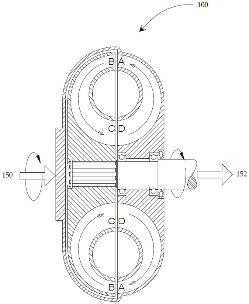
The invention discloses a hydraulic coupler for a continuously variable transmission and a coupling method. The hydraulic coupler includes a pump having a first semi-torus and a turbine having a second semi-torus. The first and second semi-toroidal bodies together form a toroidal body. A first set of fluid guide vanes is disposed radially at the first semicircular body. A first set of blades extends from the rim of the first semi-torus and terminates at a region proximate the hub of the first semi-torus. A second set of fluid guide vanes is disposed radially at the second semicircular body. A second set of blades extends from the rim of the second semi-torus and terminates at a region proximate the hub of the second semi-torus. The hydrodynamic coupling device is configured to decouple the negative coupling effect and provide a continuously variable transmission.

Description

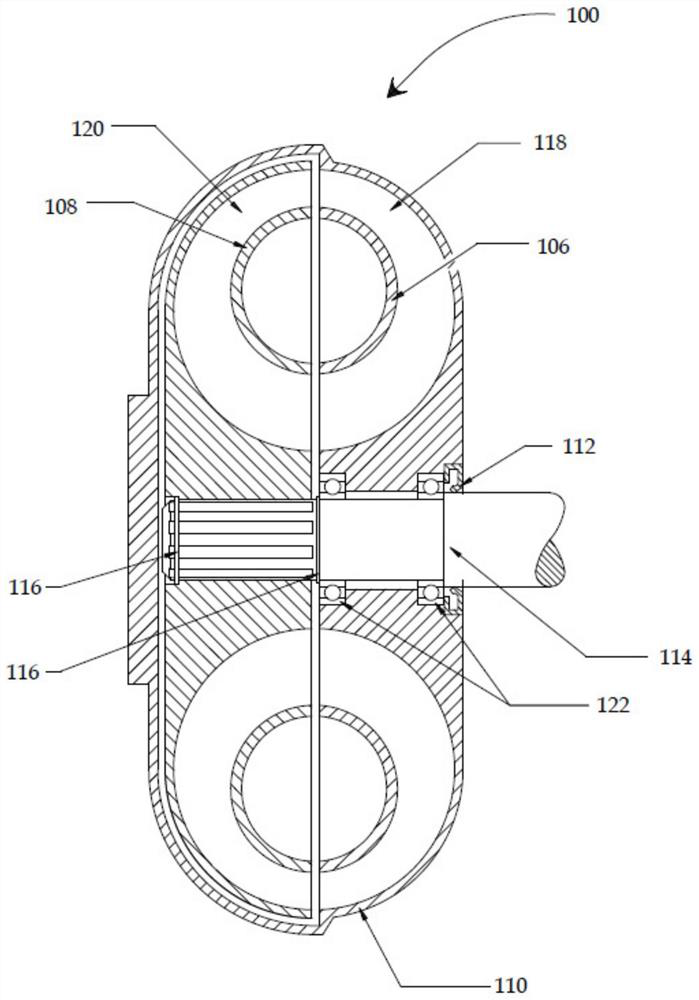
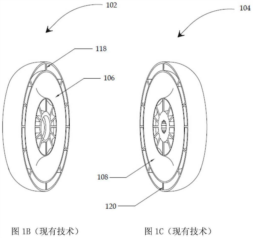
technical field [0001] The present invention generally relates to a fluid coupling and coupling method for a continuously variable transmission. Background technique [0002] Fluid couplings have been used as power transmission couplers in ships, industrial machinery and automobiles. Referring to FIGS. 1A-1C , a fluid coupling 100 includes two main components, a pump 102 and a turbine 104 . The pump 102 and turbine 104 are configured in the shape of a semi-torus having a plurality of flat blades (118, 120) extending radially from the hub to the rim of the semi-torus. Splitter guide rings ( 106 , 108 ) having a semi-toroidal shape are disposed between the hub and rim of the pump 102 and turbine 104 . The split guide rings (106, 108) are configured to prevent turbulence in the flow. Housing 110 encloses both pump 102 and turbine 104 and is filled with hydraulic fluid. Housing 110 is typically made as an integral part of pump 102 . The housing 110 rotates at the same speed...

Claims


Application Information

Patent Timeline
IPC IPC(8): F16H41/26F16D33/00F16D33/18F16D33/20F16H41/04F16H41/24
CPCF16D33/20F16H41/04
Inventor 沙达蓬·苏普里查科
Owner 沙达蓬·苏普里查科
Learn More