Integrated exhaust manifold cooling jacket

A technology for exhaust manifolds and cooling jackets, applied in liquid cooling, exhaust devices, engine cooling, etc., can solve problems such as easy cracking, difficult sealing, and partial boiling of vapor entrapment, so as to reduce flow requirements and size Effect

Pending Publication Date: 2022-05-20
FORD GLOBAL TECH LLC
View PDF1 Cites 0 Cited by
  • Summary
  • Abstract
  • Description
  • Claims
  • Application Information

AI Technical Summary

Problems solved by technology

Additionally, these temperatures will result in difficult seals, prone to cracking and transfer of excessive temperatures to the turbocharger flange
Additionally, stacked exhaust paths present challenges for coolant vapor management, as it is difficult to degas packages leading to all cooling jackets through a single degas port
If the vapor cannot be removed with the flow of the coolant, the resulting vapor entrapment can lead to localized boiling

Method used


Image

  • Integrated exhaust manifold cooling jacket
  • Integrated exhaust manifold cooling jacket
  • Integrated exhaust manifold cooling jacket

Examples


Embodiment Construction

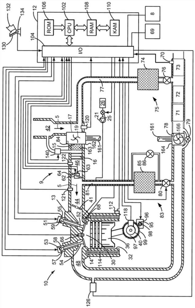
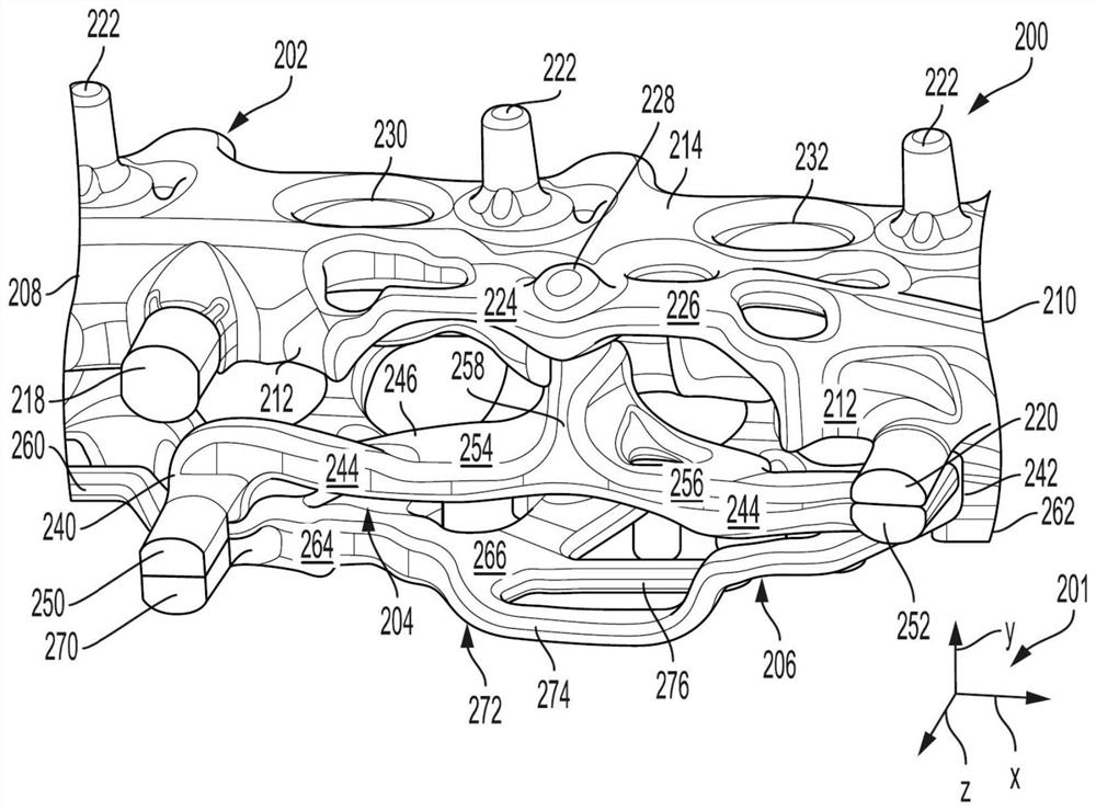
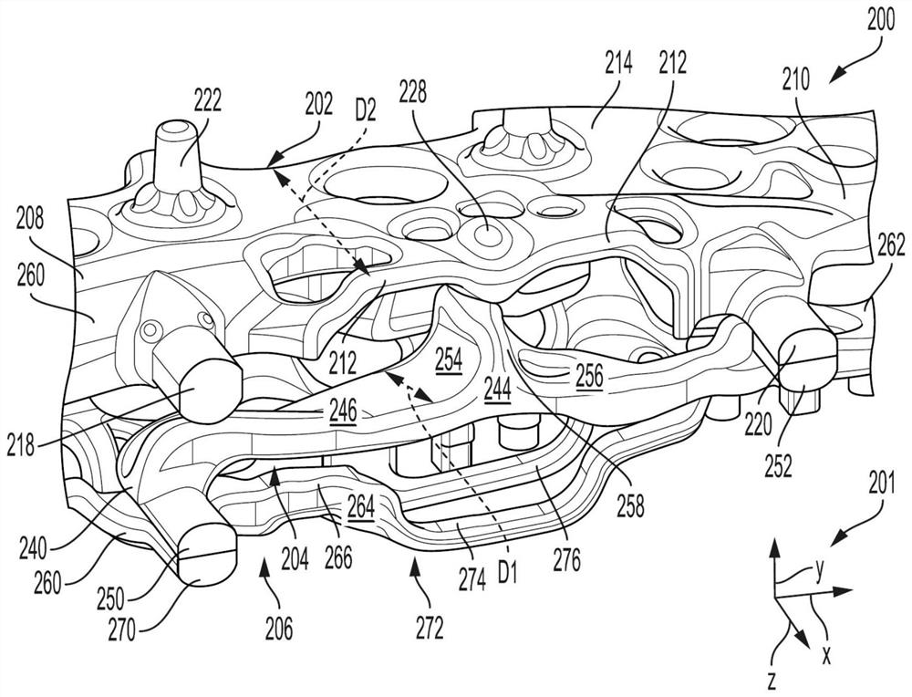
[0018] The following description refers to vehicles such as figure 1 the exhaust system of the vehicle shown). The exhaust system includes an integrated exhaust manifold comprising three exhaust passages integrated in the cylinder head, such as Figure 13 shown. The exhaust passages may be arranged in close proximity with narrow spaces in between. The integrated exhaust manifold may include an upper cooling jacket positioned on a vertical top of the exhaust passage and a lower cooling jacket positioned on a vertical bottom of the exhaust passage. The central cooling jacket can be positioned between the upper cooling jacket and the lower cooling jacket, such as Figure 2 to Figure 6D shown, and positioned between the exhaust passages of the integrated exhaust manifold, as Figure 7 to Figure 8 shown. The center cooling jacket and the upper cooling jacket may be fluidly coupled through drilled passages leading to degassing ports to exhaust coolant gases such as Figure 9 t...


PUM


Abstract

The present disclosure provides an integrated exhaust manifold cooling jacket. A system for an integrated exhaust manifold cylinder head is provided. In one example, an exhaust manifold for a vehicle includes: a plurality of exhaust runners coupling a plurality of cylinder exhaust outlet ports to an exhaust outlet port, the plurality of exhaust runners forming at least a first exhaust passage and a second exhaust passage at the exhaust outlet port; an upper cooling jacket positioned vertically above the first exhaust passage; a lower cooling jacket positioned vertically below the second exhaust passage; and a central cooling jacket positioned vertically below the first exhaust passage and vertically above the second exhaust passage.

Description

technical field [0001] The present specification relates generally to a cylinder head for a vehicle, and more particularly, to a cylinder head including an integrated exhaust manifold with a central cooling jacket. Background technique [0002] Exhaust manifolds for internal combustion engines can be exposed to high thermal loads. Exhaust manifolds integrated into the cylinder head, referred to as integrated exhaust manifold (IEM) cylinder heads, can be subject to particularly high thermal loads due to the heat transfer characteristics of the integrated design. For example, an IEM cylinder head may include an exhaust outlet port with one or more exhaust passages that is subjected to high thermal loads during operation of the vehicle. [0003] By incorporating a cooling jacket into the cylinder head, the thermal load on the integrated exhaust manifold and adjacent components can be reduced. The cooling jacket in which the coolant core is formed may reduce thermal stress on ...

Claims


Application Information

Patent Timeline
IPC IPC(8): F01N13/10F01N3/02
CPCF01N13/102F01N13/105F01N3/02F01N2470/16F01N13/1888F02F1/40F02F1/243F01P2060/16F01P3/12F01P3/02F01P2003/024F01N13/10F01P3/20
Inventor J·弗鲁哈蒂F·赫吉P·谢皮亚尔C·拉姆斯比J·拉克鲁瓦
Owner FORD GLOBAL TECH LLC
Why Eureka
Try Eureka