
Gas line combination monitoring device and system

A monitoring device and gas line technology, which is applied to measuring devices, mapping and navigation, measuring inclination, etc., can solve the problems of difficult installation process, inconvenience in popularization and use, and high production costs.

Pending Publication Date: 2022-05-20
CHINA ELECTRIC POWER RES INST
View PDF0 Cites 0 Cited by
  • Summary
  • Abstract
  • Description
  • Claims
  • Application Information

AI Technical Summary

Problems solved by technology

However, the existing monitoring equipment not only has a single function, but also has high production costs, is expensive, and is not easy to promote and use, and different types of sensors are independent and installed in a scattered manner. This structure of the system has brought many difficulties to the installation. , but also affect the quality of data collection, increasing the risk of the sensor being affected by the external environment
[0003]Existing equipment generally monitors the tower alone. The structure of the equipment is complex. The installation process is affected by the experience of the personnel and the status of the site. Soft, not conducive to installation, the installation process is relatively difficult, and the installation time is relatively long, so there is an urgent need for an easy-to-install tower monitoring system

Method used


Image

  • Gas line combination monitoring device and system
  • Gas line combination monitoring device and system
  • Gas line combination monitoring device and system

Examples


Embodiment 1

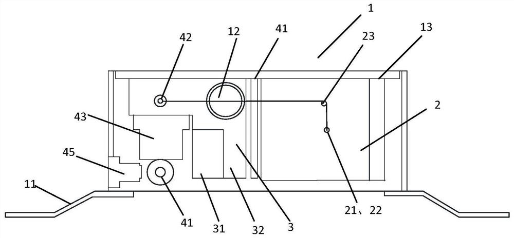
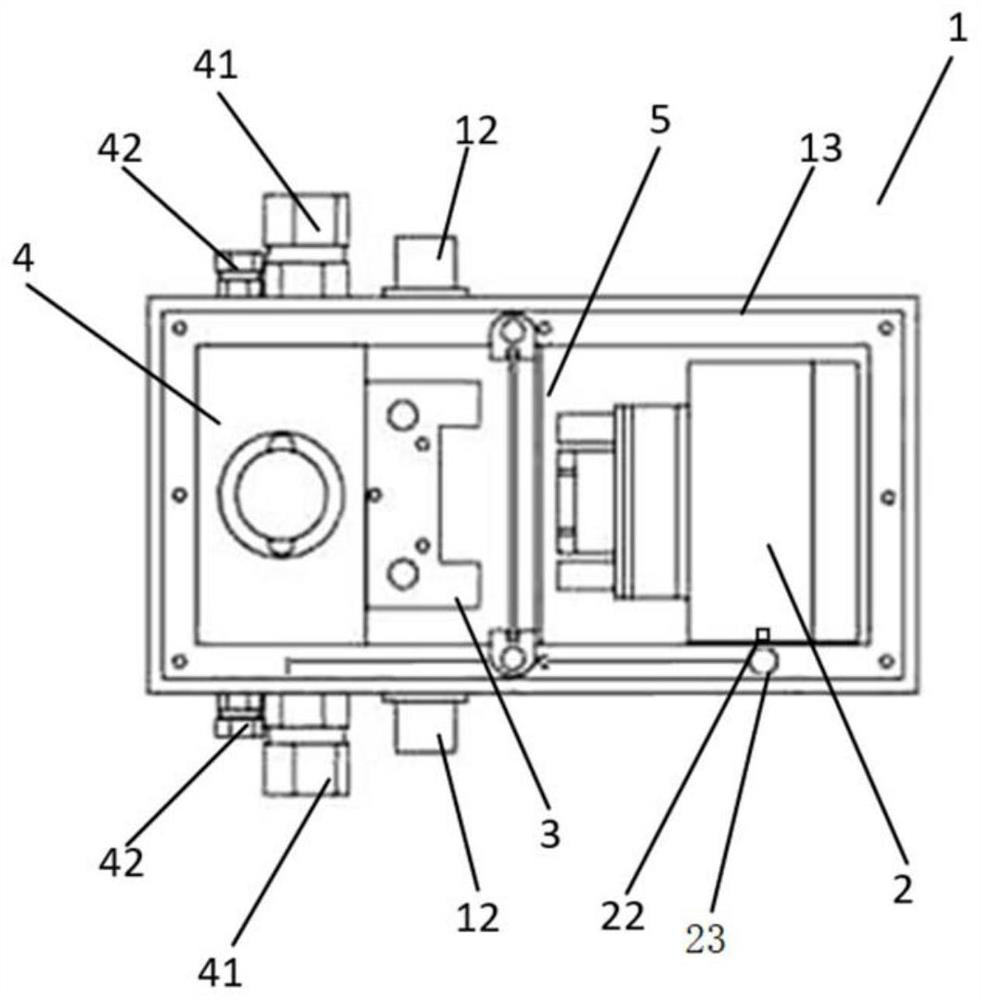
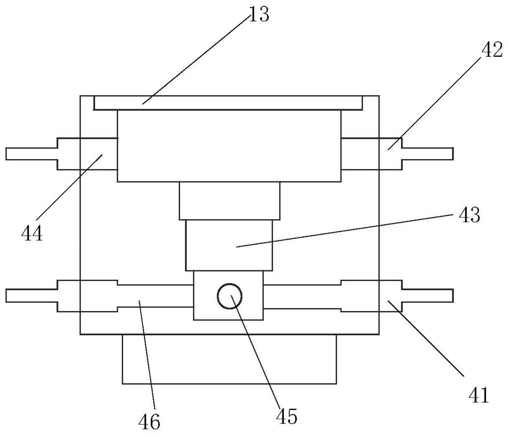
[0054] A gas line merge monitoring device 1 provided by the present invention (or simply referred to as device 1), its internal front view, internal top view, internal side view and perspective view, respectively as follows figure 1 , figure 2 , image 3 and Figure 4 As shown, it includes: a housing 13, a pull-wire displacement gauge 2, an inclinometer 3, a level 4 and a circuit unit 5;

[0055] The guyed displacement gauge 2, the inclinometer 3, the level 4 and the circuit unit 5 are respectively installed in the housing 13; the leveler 4 and the guyed displacement gauge 2 are connected through the air hole 21 on the housing 13;

[0056] The signal output terminals of the guyed displacement gauge 2, the inclinometer 3 and the level gauge 4 are connected to the circuit unit 5;

[0057] The circuit unit 5 is used to receive and process the output signals of the guyed displacement gauge 2, the inclinometer 3 and the level gauge 4, and generate transmission signals for uploa...

Embodiment 2

[0075] The gas line combined monitoring system, the schematic diagram of its connection relationship is as follows: Figure 5 As shown, it includes several gas line merger monitoring devices 1, power supply and data collectors 6 and several connectors as described in Embodiment 1;

[0076] A plurality of gas line combined monitoring devices 1 arranged on the preset monitoring points of the pole tower 9 are connected to form a connection circuit through a plurality of connectors according to the set sequence, and then connected to the power supply and data collector 6 to form a circuit;

[0077] The plurality of gas line combined monitoring devices 1 are used to obtain tower attitude data, which are uploaded to the power supply and data collector 6 after preliminary analysis;

[0078] The power supply and data collector 6 is used to process and send the tower attitude data uploaded by several gas line merge monitoring devices 1 ; it is also used to supply power to several gas l...


PUM


Abstract

The invention provides a gas line merging monitoring device and system.The gas line merging monitoring device (1) comprises a shell (13), a stay wire type displacement meter (2), an inclinometer (3), a level gauge (4) and a circuit unit (5); the guyed displacement meter (2), the inclinometer (3), the level gauge (4) and the circuit unit (5) are respectively arranged in the shell (13); the level gauge (4) is connected with the stay wire type displacement meter (2) through an air hole (21) in the shell (13); signal output ends of the guyed displacement meter (2), the inclinometer (3) and the level gauge (4) are connected with the circuit unit (5); the circuit unit (5) is used for receiving and processing the output signal and uploading the output signal; the height difference, the displacement and the inclination angle can be measured at the same time; the stay wire of the stay wire type displacement meter (2) is arranged in the air hole (21) connected with the level gauge (4), so that the stay wire can be mounted through the air pipe (44) of the level gauge (4), the mounting process is simplified, and the cost is saved.

Description

technical field [0001] The invention belongs to the technical field of geological disaster monitoring, and in particular relates to a gas line merger monitoring device and system. Background technique [0002] Geological disasters have the characteristics of randomness, diversity, and difficulty in timely detection. The occurrence of geological disasters will cause serious consequences and endanger people's lives and property. If real-time and accurate monitoring can be carried out, the loss of life and property will be avoided. . In the field of engineering construction, monitor technology provides a strong basis for the design of new buildings and the monitoring of old buildings, and the endless engineering safety monitoring instruments gradually fill the gaps in this field. The current monitoring equipment can conduct continuous automatic monitoring, distribute network points in regions or arrange monitoring points in key areas for online monitoring. However, the existi...

Claims


Application Information

Patent Timeline
Patent Type & Authority Applications(China)
IPC IPC(8): G01D21/02G01C5/04G01C9/00G01B21/02
CPCG01D21/02G01C5/04G01C9/00G01B21/02
Inventor 刘毅赵斌滨杨知程永锋孔小昂刘彬李孟轩赵彬
Owner CHINA ELECTRIC POWER RES INST
Learn More