
Novel water pump

A water pump, a new type of technology, applied in the direction of pumps, pump control, pump components, etc., can solve the problems of insufficient energy saving, waste of motor power, etc.

Inactive Publication Date: 2022-05-24
乔亚军
View PDF0 Cites 0 Cited by
  • Summary
  • Abstract
  • Description
  • Claims
  • Application Information

AI Technical Summary

Problems solved by technology

[0003] Therefore, the head of the existing centrifugal pump is closely related to the structure of the blades on the impeller. The blades on the existing impeller are connected in a fixed way, so the head of a centrifugal pump is fixed, and the centrifugal pump is used for different thicknesses. When the liquid is used, the output power requirements of the motor will not be the same. For example, when the blade structure adopts a curved sheet structure, since there is an extrapolated thrust during the rotation process, the motor shaft needs to overcome more resistance. So that the liquid can be thrown out better, so it is more suitable for thicker liquids, and when the liquid is not very thick, the blades with straight plate structure can effectively reduce the resistance that the motor shaft needs to overcome. Then reduce the output power of the motor, so as to achieve the effect of energy saving, but in the prior art, due to the unchangeable characteristics of the blade structure, it will appear that when the curved sheet structure is applied to the liquid with low consistency, compared with the straight plate Chip structure will waste more motor power, so there is not enough energy saving

Method used


Image

  • Novel water pump
  • Novel water pump
  • Novel water pump

Examples


Embodiment Construction

[0022] The present invention will be described in further detail below in conjunction with the embodiments given in the accompanying drawings.

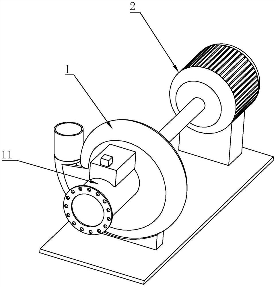
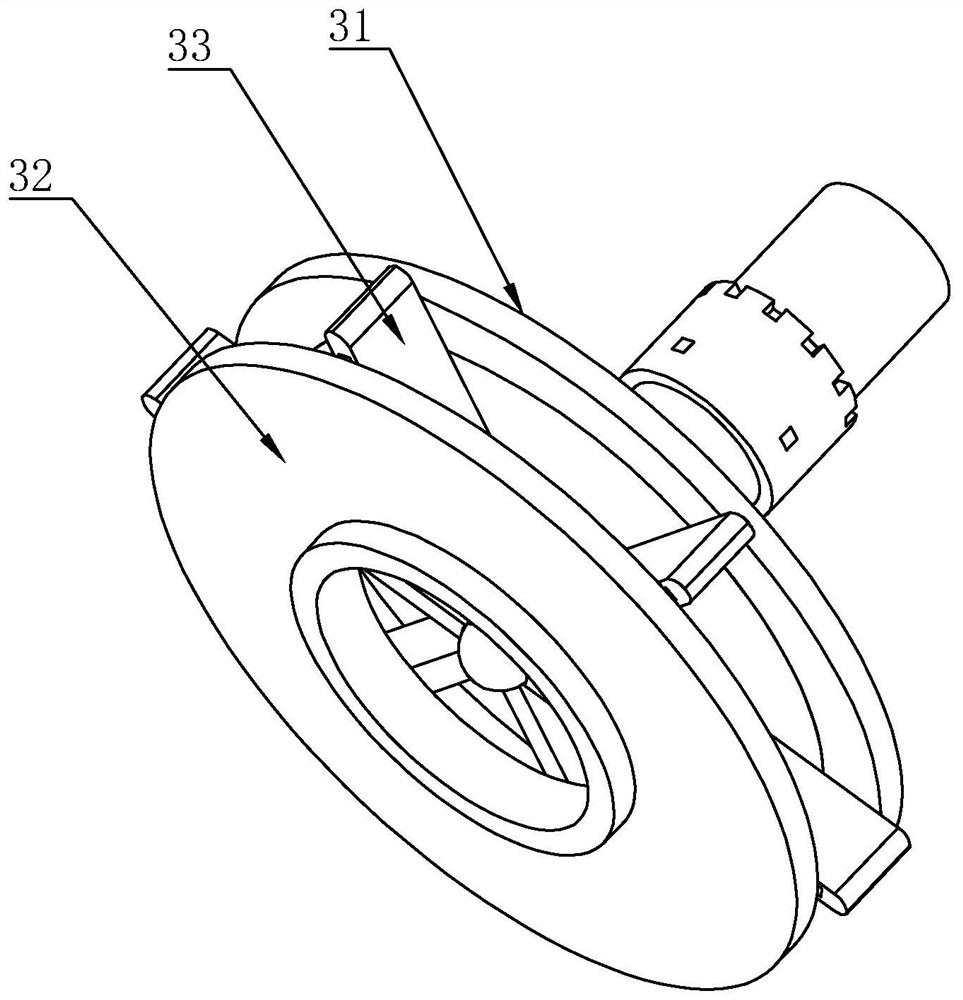
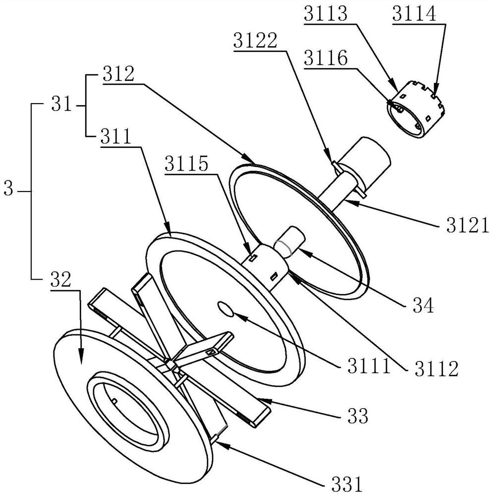
[0023] refer to Figures 1 to 7 As shown, a new type of water pump in this embodiment includes a pump housing 1, a motor 2 and an impeller 3, the impeller 3 is coaxially fixed on the rotating shaft of the motor 2, and is rotatably arranged in the pump housing 1. The impeller 3 includes a chassis 31, a cover plate 32 and several blades 33. A through hole 321 is opened at the center of the cover plate 32, and the through hole 321 communicates with and seals the liquid inlet of the pump casing 1. The cover plate 32 is coaxially connected with the chassis 31, the hub of the chassis 31 is coaxially fixed with a blade shaft 34, and one end of several blades 33 is fixed on the blade shaft 34, and the blade shaft 34 is used as the center of the circle to form a circular uniform distribution The chassis 31 includes a fixed plate 311 and a mov...


PUM


Abstract

The novel water pump comprises a pump shell, a motor and an impeller, the impeller is coaxially fixed to a rotating shaft of the motor, the impeller comprises a base plate, a cover plate and a plurality of blades, a through hole is formed in the center of the cover plate, the through hole and a liquid inlet of the pump shell are mutually communicated and sealed, the cover plate is coaxially connected with the base plate, and the cover plate is coaxially connected with the base plate. A blade shaft is coaxially fixed to the center of the base plate, the base plate comprises a fixed plate and a movable plate, the movable plate is coaxially and rotatably arranged on the end face, opposite to the cover plate, of the fixed plate, the blade shaft is coaxially fixed to the circle center of the end face of the movable plate, and the ends, opposite to the blade shaft, of the blades are connected with connecting columns. The two ends of the connecting column are fixedly connected with the fixed disc and the cover disc respectively, and the blades can be bent. According to the novel water pump, through the bendable arrangement of the blades, the energy-saving effect is effectively achieved.

Description

technical field [0001] The invention relates to a centrifugal pump structure, and more specifically relates to a new type of water pump. Background technique [0002] Centrifugal pump is a water pump that is frequently used in daily life. Its main working principle is that through the high-speed rotation of the impeller in the pump casing, the blades on the impeller drive the water to make a circular motion, and the water will be in the process of circular motion due to the centrifugal force. Throw it out, and then output it to the outside through the water outlet on the pump casing, a vacuum will be formed in the center of the impeller, so it will continue to suck in the water source, and in turn realize the effect of circular pumping. [0003] Therefore, the head of the existing centrifugal pump is closely related to the structure of the blades on the impeller. The blades on the existing impeller are connected in a fixed way, so the head of a centrifugal pump is fixed, and...

Claims


Application Information

Patent Timeline
IPC IPC(8): F04D13/06F04D15/00F04D29/24
CPCF04D13/06F04D29/24F04D29/242F04D29/247F04D15/0088F04D15/0055
Inventor 乔亚军
Owner 乔亚军
Learn More