High-voltage rectification integrated transformer
A high-voltage rectification and transformer technology, applied in the field of transformers, can solve the problems of transformer damage, lack of rain and snow protection, poor shock absorption effect, etc., and achieves the effect of extending service life, facilitating removal, and reducing severe vibration.
- Summary
- Abstract
- Description
- Claims
- Application Information
AI Technical Summary
Problems solved by technology
Method used
Image
Examples
Embodiment 1
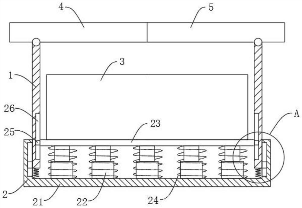
[0020] Reference Figure 1-5 , a high-voltage rectifier integrated transformer, including box 1, transformer body 3, first baffle 4 and second baffle 5, transformer body 3 is provided in the interior of the box 1, the first baffle 4 is hinged to the upper end of the box 1, the second baffle 5 is hinged to the other side of the upper end of the box 1, and the first baffle 4 and the second baffle 5 is relatively set, the lower end of the box 1 is provided with a shock absorbing base 2, and the shock absorbing base 2 is connected to the transformer body 3, through the setting of the shock absorbing base 2, In this way, it can play a shock absorption effect on transformer body 3, which in turn can reduce the violent vibration generated by transformer body 3 during operation, and can effectively extend the service life of transformer body 3.
[0021] The first baffle 4 and the second baffle 5 articulation at one end is connected to the transmission mechanism, and the transmission mechan...
Embodiment 2
[0023] Reference Figure 1 、 Figure 4 and Figure 5, as another preferred embodiment of the present invention, the difference with Example 1 is that the shock absorbing base 2 includes a connection slot 21, several telescopic rods 22, a connection plate 23, a plurality of first springs 24 and several second springs 27, the connection slot 21 is provided at the lower end of the box 1, and the lower end of the box 1 is located inside the connection slot 21, several telescopic rods 22 are fixed to the inner bottom of the connection slot 21, the connection plate 23 is fixed to the upper end of several telescopic rods 22, And the transformer body 3 is fixedly connected to the upper surface of the connection plate 23, both ends of the connection plate 23 are connected to both sides of the inner wall of the box 1 through the first sliding mechanism, the first sliding mechanism comprises the first slider 25 and the first chute 26, the first slider 25 is fixedly connected to the end of the c...
Embodiment 3
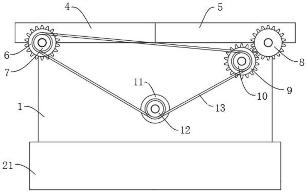
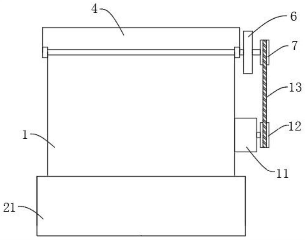
[0028] Reference Figure 2-3 , as another preferred embodiment of the present invention, the difference with Example 1 is that the transmission mechanism comprises a first gear 6, a first pulley 7, a second gear 8, a third gear 9, a second pulley 10, a motor 11, a third pulley 12 and a belt 13, a first gear 6 fixed connection to one end of the first baffle 4 articulation, a first pulley 7 fixed to the first gear 6, a second gear 8 fixed to the second baffle 5 articulation at one end, the third gear 9 rotation connected to the outer side wall of the box 1, The second pulley 10 is fixed to the third gear 9, the motor 11 is fixed to the outer wall of the box 1, the motor 11 is connected to the external power supply device by a wire, and the wire is provided with a switch to control the operation of the motor 11, the motor 11 uses a servo motor.
[0029] The third pulley 12 is fixedly connected to one end of the output shaft of the motor 11, the belt 13 is connected to the first pulley...
PUM
 Abstract
Description
Claims
Application Information
 - R&D
- Intellectual Property
- Life Sciences
- Materials
- Tech Scout
- Unparalleled Data Quality
- Higher Quality Content
- 60% Fewer Hallucinations
Browse by: Latest US Patents, China's latest patents, Technical Efficacy Thesaurus, Application Domain, Technology Topic, Popular Technical Reports.
© 2025 PatSnap. All rights reserved.Legal|Privacy policy|Modern Slavery Act Transparency Statement|Sitemap|About US| Contact US: help@patsnap.com


