Ultrasonic welding device and ultrasonic welding method

An ultrasonic welding and welding part technology, applied in welding/welding/cutting items, welding equipment, non-electric welding equipment, etc., can solve the problems of low welding yield, loss of foil tab edges, etc., and achieve the effect of avoiding rupture

Pending Publication Date: 2022-05-27
WANXIANG 123 CO LTD
View PDF10 Cites 0 Cited by
  • Summary
  • Abstract
  • Description
  • Claims
  • Application Information

AI Technical Summary

Problems solved by technology

[0003] The purpose of the present invention is to overcome the problem that the welding head is easy to cause loss to the edge of the foil tab during the welding process of the existing lithium battery, resulting in low welding yield, and to provide a method that helps to reduce the damage of the welding head to the edge of the foil tab. Small ultrasonic welding device and ultrasonic welding method

Method used


Image

  • Ultrasonic welding device and ultrasonic welding method
  • Ultrasonic welding device and ultrasonic welding method
  • Ultrasonic welding device and ultrasonic welding method

Examples


Embodiment 1

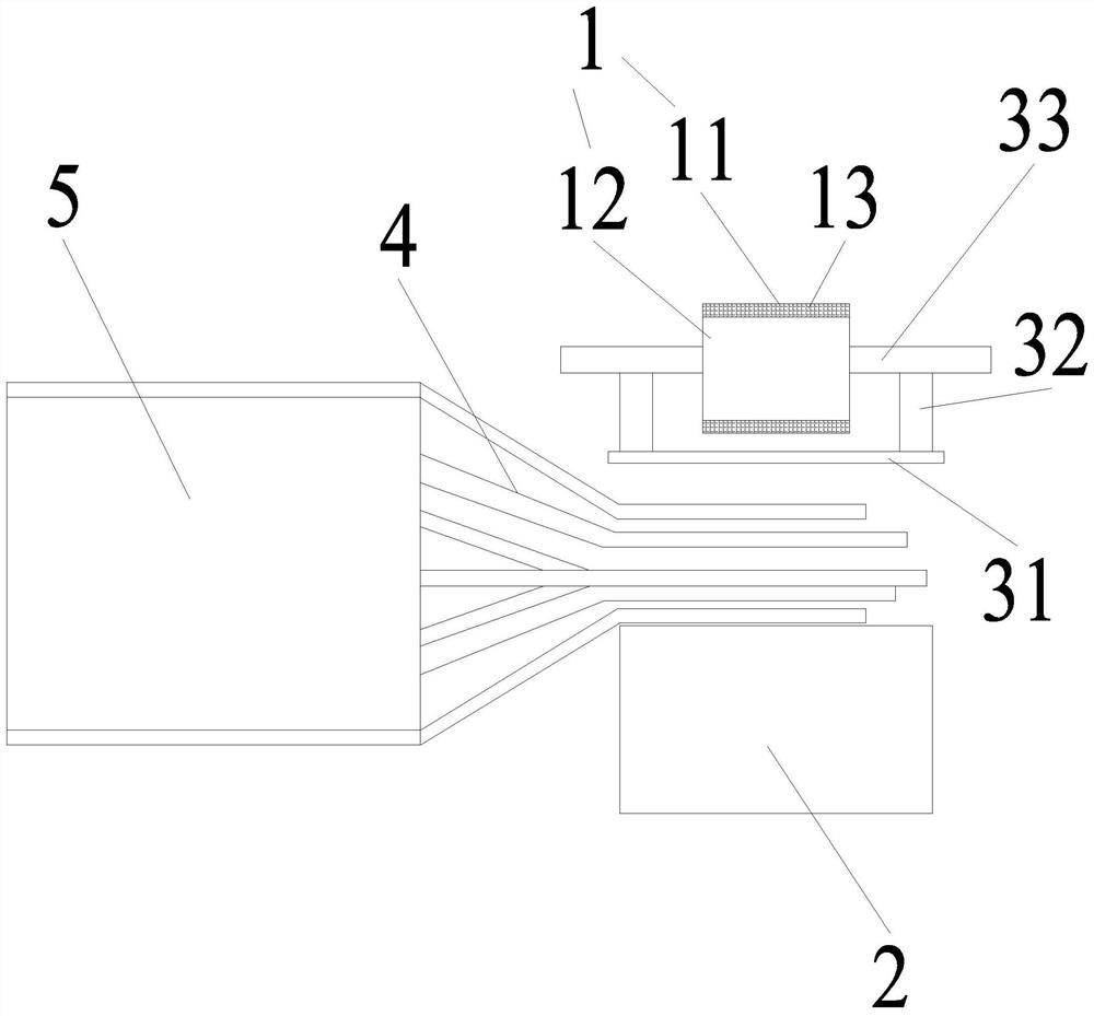
[0030] like Figures 1 to 6 As shown, an ultrasonic welding device includes a welding head 1 and a welding seat 2. The welding head 1 is provided with welding parts 11 on two symmetrical sides, and the welding parts 11 are connected by a connecting part 12. There are several welding teeth 13 arranged at intervals, the welding teeth 13 include a first surface 131 fixedly connected with the welding part 11 and a second surface 132 away from the welding part 11 , the welding teeth 13 are arranged in order to form a gap 14 of straight bars.

[0031] A new ultrasonic welding tooth arrangement design is adopted, and a gap 14 is provided on the originally regularly arranged welding teeth 13, which helps to weaken the welding teeth 13 on the edge of the welding part 11 during the welding process of the welding head 1. The pair of tab foils 4, to avoid the problem of rupture of the tab foil 4, resulting in a low product qualification rate.

[0032] Specifically, the number of welding...

Embodiment 2

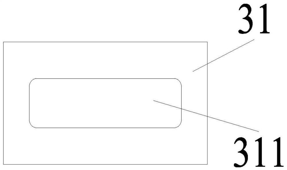
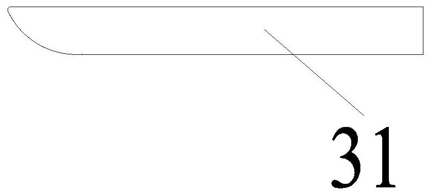
[0043] like Figures 7 to 9 As shown, an ultrasonic welding device includes a welding head 1 and a welding seat 2. The welding head 1 is provided with welding parts 11 on two symmetrical sides, and the welding parts 11 are connected by a connecting part 12. There are several welding teeth 13 arranged at intervals, the welding teeth 13 include a first surface 131 fixedly connected with the welding part 11 and a second surface 132 away from the welding part 11 , the welding teeth 13 are arranged in order to form a gap 14 of straight bars. The welding head 1 is provided with a liftable pressing device. The pressing device includes a pressing plate 31, a telescopic rod 32 and a mounting base plate 33 fixedly connected to the connecting portion 12 of the welding head 1. One end of the telescopic rod 32 is connected to the mounting plate 33. The bottom plate 33 is fixedly connected, and the other end of the telescopic rod 2 is fixedly connected to the pressing plate 31 . The conta...


PUM

PropertyMeasurementUnit
thicknessaaaaaaaaaa

Abstract

The invention discloses an ultrasonic welding device and an ultrasonic welding method, the ultrasonic welding device comprises a welding head and a welding seat, two symmetrical sides of the welding head are provided with welding parts, the welding parts are connected through a connecting part, the welding parts are internally provided with a plurality of welding teeth arranged at intervals, and the welding teeth are neatly arranged to form a straight strip with a notch. According to the invention, the damage of the welding teeth at the edge of the welding part to the tab foil is reduced, the problem of tab foil breakage is avoided, and the product percent of pass is improved.

Description

technical field [0001] The invention relates to the technical field of lithium battery pole piece foil connection, in particular to an ultrasonic welding device and an ultrasonic welding method. Background technique [0002] The pole piece foil is drawn out from one end of the pole piece of each lithium battery. After the pole piece is drawn out, the pole piece foils on each pole piece are superimposed and welded together to form a conductive end, which is then connected to the tab, which is then connected to the stage post. At present, the tab welding method of laminated soft-pack lithium battery generally adopts ultrasonic welding to pre-weld the lead-out foils between the pole pieces together to form a pre-welded foil, and then ultrasonically weld the tab metal to the pre-welded foil. The solder foils are welded together to achieve the purpose of welding. However, in the process of ultrasonic welding, since the thickness of the foil drawn by the pole piece is very small,...

Claims


Application Information

Patent Timeline
Patent Type & Authority Applications(China)
IPC IPC(8): B23K20/10B23K20/26B23K101/36
CPCB23K20/10B23K20/26B23K2101/36Y02E60/10
Inventor 赵星星饶绍建张富韩笑李凡群
Owner WANXIANG 123 CO LTD
Why Eureka
Try Eureka