Eureka AIR delivers breakthrough ideas for toughest innovation challenges, trusted by R&D personnel around the world.

Visual calibration method for manipulator flowing along production line

A calibration method and manipulator technology, applied in the field of visual calibration, can solve problems such as difficulty in improving manipulator tempo, achieve the effect of shortening work tempo and improving production efficiency

Pending Publication Date: 2022-05-27
NINGBO JIUZONG INTELLIGENT TECH
View PDF0 Cites 0 Cited by
  • Summary
  • Abstract
  • Description
  • Claims
  • Application Information

AI Technical Summary

Problems solved by technology

[0005] In view of the defects in the prior art that the manipulator must wait for the product to stop flowing on the production line before it can work, making it difficult to improve the beat of the manipulator, the present invention provides a visual calibration method for the manipulator to follow the flow of the production line

Method used


Image

  • Visual calibration method for manipulator flowing along production line
  • Visual calibration method for manipulator flowing along production line

Examples


Embodiment 1

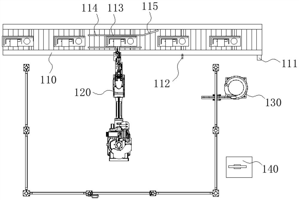
[0031] like figure 1 As shown, this embodiment provides a visual guidance device for manipulators to follow the flow of the production line, which includes an assembly line 110 and a manipulator 120. The manipulator 120 is used to follow the flow of the assembly line 110, thereby realizing the tracking of the products to be processed so as to realize the production of the products to be processed. Dynamic processing (including assembly and disassembly); one side of the manipulator 120 is provided with a feeding mechanism 130 and an electric control cabinet 140, and the electric control cabinet 140 is used to control the manipulator 120 to track and assemble the products to be processed flowing on the assembly line 110 or disassembled.

[0032] combine figure 2 As shown, based on the above-mentioned visual guidance device for manipulators to follow the flow of the production line, this embodiment also provides a visual calibration method for the manipulators to follow the flo...


PUM


Abstract

The invention relates to the technical field of visual calibration, in particular to a visual calibration method for a manipulator flowing along with a production line, which comprises the following steps of: S1, taking t0 as an initial moment, and acquiring offset delta x, offset delta y and offset angle theta between the position of the manipulator and a product to be processed at the initial moment t0; s2, calculating the motion stroke x (t) of the manipulator in the first running direction and the motion stroke y (t) of the manipulator in the second running direction at the current moment t; under the condition that flow of the assembly line is achieved, the processes of blocking mechanisms such as an air cylinder and enabling products to stop acting are omitted, the mechanical arm is made to flow along with the assembly line, dynamic assembly or disassembly is achieved, the working rhythm of the mechanical arm is improved, and the production efficiency is improved.

Description

technical field [0001] The invention relates to the technical field of visual calibration, in particular to a visual calibration method in which a manipulator follows the flow of a production line. Background technique [0002] With the increase of my country's air-conditioning output, the hourly output of the assembly line is also required to be higher and higher. For example, some assembly lines have reached an output of 330 units per hour, but this hourly output has reached the physiological limit of workers and is unsustainable. [0003] The current assembly line has vision-guided six-axis robot-operated equipment, such as automatically dismantling the angle valve of the air conditioner external unit, automatically removing screws or glue, and loading the compressor. However, the cylinder needs to block the air conditioner external unit during the dismantling process to stop , resulting in the delay of the manipulator waiting to block the cylinder and other actions, so t...

Claims


Application Information

Patent Timeline
Patent Type & Authority Applications(China)
IPC IPC(8): B25J9/16G06V20/00
CPCB25J9/1697B25J9/1664B25J9/1687B25J9/1602Y02P90/02
Inventor 王孟哲梁正南赖勉力李恩全
Owner NINGBO JIUZONG INTELLIGENT TECH
Why Eureka
Eureka Blog
Learn More