[0034] In order to make the object, technical solution and advantages of the present invention clearer, the embodiments of the present invention will be further described in detail below in conjunction with specific embodiments and with reference to the accompanying drawings.
[0035] It should be noted that all expressions using "first" and "second" in the embodiments of the present invention are to distinguish two entities with the same name but different parameters or parameters that are not the same, see "first" and "second" It is only for the convenience of expression, and should not be construed as a limitation on the embodiments of the present invention, which will not be described one by one in the subsequent embodiments.
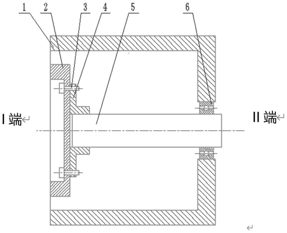
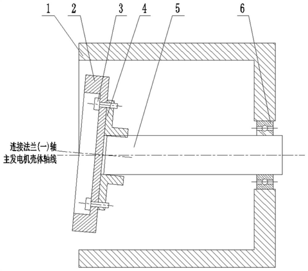
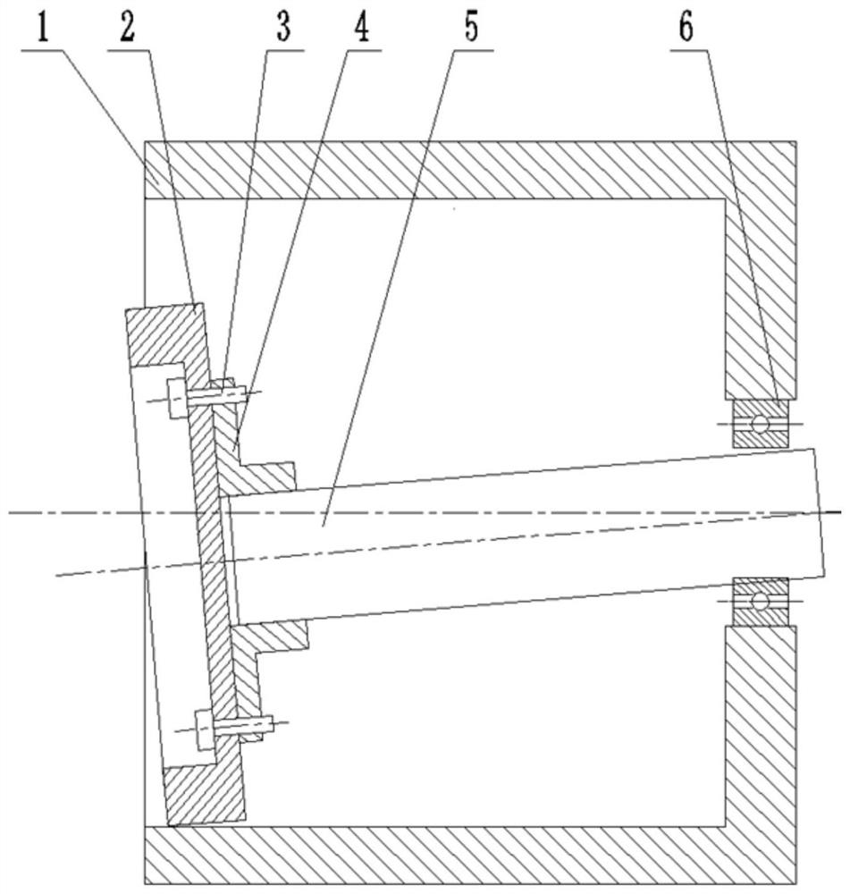
[0036] like Figure 4-Figure 8 As shown, some embodiments of the present invention disclose a method for detecting the assembly coaxiality of a diesel generator set, including the following steps:
[0037] Step 1: adjust the position of the rotor connection flange 2 of the main generator so that the rotor connection flange 2 is concentric with the housing installation end face of the main generator;
[0038] Step 2 Measure the distance between the mounting end face of the main generator casing and the mounting end face of the rotor connecting flange 2 of the main generator at different positions in the circumferential direction, and calculate the distance between the mounting end face of the rotor connecting flange 2 and the casing based on the distance. The inclination angle between the installation end surfaces is used as the evaluation standard for the coaxiality between the rotor connecting flange 2 and the installation surface of the main generator housing 1 .
[0039] Wherein, adjusting the position of the rotor connecting flange 2 of the main generator may include: inserting a plug 7 in the gap between the rotor connecting flange 2 and the casing of the main generator, and adjusting the insertion of the plug 7 depth, the plugs 7 are respectively arranged at the lower end and both sides of the rotor connecting flange 2 .
[0040] The plug 7 needs to have a small end for inserting between the outer wall of the connecting flange and the inner wall of the main generator casing 1, and a large end arranged relative to the small end; the first contact surface and the small end of the second contact surface are the small ends of the block 7 .
[0041] The plug 7 includes a first contact surface for abutting against the outer wall of the rotor connecting flange 2, and a second contact surface for abutting against the inner wall of the main generator housing 1, wherein the first The contact surface includes a concave first arc surface, the small end of the first contact surface is in contact with the small end of the second contact surface, and the large end of the first contact surface is in contact with the large end of the second contact surface. There is a first distance between them. The first arc surface is roughly fan-shaped, and the first contact surface further includes a first plane formed by extending the large end of the first arc surface. Both sides of the first contact surface and the second joint contact surface are connected by two side surfaces. A line connecting the large end and the small end of the first arc surface forms a first included angle with the second contact surface, and the first included angle is 20° (20°±1°). The concave curve of the first arc surface is adapted to the outer wall of the rotor connecting flange 2 . The extension surfaces of the two side surfaces form a second included angle, and the second included angle is 98° (98°±3°).
[0042]Adjust the insertion depth of the three plugs 7 located at the lower end and both sides of the connecting flange, and measure the width of the gap at intervals of 90° to obtain four width values, the difference between any two of the width values When it is less than 0.5mm, it is considered that the rotor connecting flange 2 is concentric with the housing installation end face of the main generator.
[0043] Further, the formula for calculating the angle of inclination is
[0044]
[0045] Wherein, θ is the angle of inclination, b is the distance between the mounting end face of the casing of the main generator and the mounting end face of the rotor connecting flange 2 of the main generator, and D is the diameter of the rotor connecting flange 2 .
[0046] The plug 7 disclosed in some preferred embodiments of the present invention, such as Figure 4 , Pic 4-1 As shown, it has a circular arc and an inclined slideway, which can better support and adjust the connecting flange 1 (rotor connecting flange 2), the plug 7 is in the shape of an inverted isosceles trapezoid, and the angle between the two waists is 98° , The large arc chamfer at the bottom can better fit and stabilize the arc of the main engine casing. The arc radius R of the block 7 slideway is the same as the radius of the connecting flange 1, and the best slope angle of the arc slideway is 20°, that is, a slope of 1:2.75. The slope is too large, which is not conducive to the insertion of the block 7 , the slope is too small, and it is not conducive to the adjustment of the connecting flange one. like Figure 5 , insert plugs 7 into the bottom and left and right sides of the connecting flange 1 respectively, and adjust the position of the connecting flange 1 through the insertion of the plugs 7 . Use a vernier caliper to measure the gap a between the connecting flange 1 and the main generator casing 1. The measurement method is to measure a point every 90°, and 4 measuring points are evenly distributed on the connecting flange 1 circumference. When the difference between any two of the gaps between the four measuring point positions is ≤0.5mm, the flange is considered to be concentric with the mounting end face of the housing.
[0047] like Image 6 As shown, measure the distance b between the mounting end face of the main generator housing 1 and the edge of the mounting end face of the connecting flange. The measurement method is to measure a point at an interval of 90°. Just measure the distance b between two symmetrical points. As shown in the figure, the diameter of connecting flange 1 is D, and the angle between the installation end surface of connecting flange 1 and the installation end surface of main generator casing 1 is θ, then
[0048]
[0049] Depend on Image 6 It can be seen that the included angle between the axis of the connecting flange 1 and the axis of the main generator housing 1 is θ, so the angle θ can be used as an evaluation standard for the coaxiality of the connecting flange 1 and the installation surface of the main generator housing 1 . According to experience, when θ≤0.3°, it means that the coaxiality between the connecting flange 1 and the main generator casing 1 meets the installation requirements.
[0050] The included angle θ reflects the proportional relationship between b and D. For connecting flanges with different diameters D, θ≤0.3° can be used as the evaluation standard. The included angle θ is obtained by calculation. For the convenience of practical operation, the corresponding installation end face distance b limit can be calculated for the commonly used connection flange diameter D. If the diameter D is known, θ≤0.3°, then
[0051]
[0052] Make measurement comparison table 1, and compare the actual measured installation end face distance b with the limit b' in the table. When b≤b', the coaxiality between connecting flange 1 and main generator casing 1 meets the installation requirements.
[0053] Table 1 Comparison table of measured values
[0054] serial number Connecting flange diameter D limit b' Actual measurementb 1 D 1
[0055] like Figure 7 As shown, the axis of the connecting flange of the main generator is completely coincident with the axis of the main generator housing 1. If the axis of the flywheel 8 of the diesel engine and the axis of the flywheel housing 9 are also completely coincident, then the mounting end surface of the connecting flange and the flywheel 8 of the diesel engine are installed The fit of the end face is good, and there is no stress caused by misalignment in the shafting of the diesel generator set. like Figure 8 As shown, the coincidence degree of the axis of the main generator connecting flange 1 and the axis of the main generator housing 1 is not good, and the installation end surface of the connecting flange 1 and the installation end surface of the flywheel 8 form an included angle α. For example, connecting flange 1 and the flywheel 8 If 8 are connected together, stress will be generated in the shafting of the diesel generator set, the shafting will not rotate smoothly, and vibration will cause damage to the components. This detection method can effectively measure the degree of coincidence between the first axis of the connecting flange and the first axis of the main generator casing, that is, whether the coaxiality can meet the requirements.
[0056] Before the diesel generator set is assembled, the coaxiality of the first axis of the connecting flange of the main generator and the axis of the housing is tested. like Figure 5 , Image 6 As shown, first plug block 7 is inserted into the bottom and left and right sides of connecting flange one, and adjust the position of connecting flange one. Use a vernier caliper to measure the gap a between the connecting flange 1 and the main generator casing 1. The measurement method is to measure a point every 90°, and 4 measuring points are evenly distributed on the connecting flange 1 circumference. When the difference between any two of the gap values of the 4 measuring points is ≤0.5mm, it is considered that the flange is concentric with the mounting end face of the shell. Then measure the distance b between the mounting end face of the main generator housing 1 and the edge of the mounting end face of the connecting flange. The measuring method is to measure a point every 90°. According to the measured value comparison table in Table 1, compare the measured value b with the limit b' to judge whether the coaxiality between the connecting flange 1 and the main generator casing 1 meets the installation requirements, otherwise, the rotor shaft 5 of the main generator needs to be checked. The concentricity is corrected.
[0057] To sum up, the method for detecting the assembly coaxiality of the diesel generator set disclosed in the embodiment of the present invention adopts a block with a circular arc and an inclined slideway to adjust the position of the connecting flange 1 of the main generator The block is an inverted isosceles trapezoid, the angle between the two waists is 98°; the arc radius of the block slideway is the same as that of the connecting flange 1, and the included angle with the horizontal plane is 20°, that is, the slope is 1:2.75; every interval of 90 °, 4 measuring points are evenly distributed on the circumference to measure the gap a between the connecting flange 1 and the main generator shell; by measuring the diameter D of the connecting flange 1, the installation end surface of the main generator shell and the connecting flange 1 are installed The distance b between the edge of the end face, and the angle between the two is calculated
[0058]
[0059] The included angle between the first axis of the connecting flange and the axis of the main generator casing is θ, and the angle θ is used as the evaluation standard for the coaxiality between the first connecting flange and the mounting surface of the main generator casing; θ≤0.3° is used as the connecting flange 1. Requirements for coaxiality with the main generator shell installation surface; prepare the table corresponding to b', D, θ,
[0060]
[0061] Simplify the calculation procedure, and judge whether the coaxiality meets the requirements by comparing the measured b with the theory.
[0062] Solved the problem that the coaxiality of the single-support main generator could not be measured; through the measurement, the main generator with poor coaxiality was eliminated, the assembly alignment accuracy of the diesel generator set was improved, the vibration was reduced, and the reliability of the diesel generator set was improved. The measurement method is simple and easy to operate, and can be operated on the construction site; the included angle θ is used as the judging standard of coaxiality, which is more intuitive; the comparison table is compiled to compare the actual measured value b, which saves the tedious calculation process and improves the work efficiency. efficiency.
[0063] It should be pointed out that the various components or steps in the above-mentioned embodiments can intersect, replace, add, and delete each other. Therefore, the combinations formed by these reasonable permutations, combinations, and transformations should also belong to the protection scope of the present invention, and should not The scope of protection of the invention should be limited to the examples described.
[0064] The above are exemplary embodiments disclosed in the present invention, and the sequence disclosed in the above embodiments of the present invention is only for description, and does not represent the advantages or disadvantages of the embodiments. However, it should be noted that the discussion of any of the above embodiments is exemplary only, and is not intended to imply that the scope (including the claims) disclosed by the embodiments of the present invention is limited to these examples. Various changes and modifications are made. The functions, steps and/or actions of the method claims in accordance with the disclosed embodiments described herein need not be performed in any particular order. In addition, although the elements disclosed in the embodiments of the present invention may be described or required in an individual form, they may also be understood as a plurality unless explicitly limited to a singular number.
[0065] Those of ordinary skill in the art should understand that: the discussion of any of the above embodiments is exemplary only, and is not intended to imply that the scope (including claims) disclosed by the embodiments of the present invention is limited to these examples; under the idea of the embodiments of the present invention , technical features in the above embodiments or in different embodiments can also be combined, and there are many other changes in different aspects of the embodiments of the present invention as described above, which are not provided in details for the sake of brevity. Therefore, any omission, modification, equivalent replacement, improvement, etc. made within the spirit and principles of the embodiments of the present invention shall be included within the protection scope of the embodiments of the present invention.