Real-time navigation method and device, unmanned vehicle, computer equipment and storage medium
A navigation method and unmanned vehicle technology, applied in the direction of measuring devices, radio wave measuring systems, instruments, etc., can solve the problems of constant speed, not too fast, easy failure at corners, etc., to improve stability and avoid control failure Effect
Pending Publication Date: 2022-05-27
GUANGZHOU XAIRCRAFT TECH CO LTD
0 Cites 0 Cited by
AI-Extracted Technical Summary
Problems solved by technology
[0004] In view of this, the embodiment of the present application provides a real-time navigation method and device based on lidar, an unmanned vehicle, computer equipmen...
Method used
According to the real-time navigation device based on laser radar provided by the application, utilize laser radar to collect the laser reflection intensity of current frame point cloud and each point, identify landmark point from current frame point cloud based on laser reflection intensity, based on landmark point Determine at least one continuous path point, and control the unmanned vehicle to travel along the at least one continuous path point. Since the point cloud collected by lidar has geographic location information, which is a true reflection of the current environment, on the one hand, the current waypoint determined based on the point cloud will not deviate too much from the previous waypoint’s driving direction, thus Improve driving stability and avoid control failure; on the other hand, based on the same frame point cloud, multiple continuous path points can be determined, avoiding the process of determining path points to limit the speed of the vehicle; on the other hand, due to the laser The point cloud collected by the radar has depth information, which ensures that the next waypoint can be accurately determined even when the speed of the vehicle changes.
According to the real-time navigation method based on laser radar provided by the application, utilize laser radar to gather the laser reflection intensity of current frame point cloud and each point, identify landmark point from current frame point cloud based on laser reflection intensity, based on landmark point Determine at least one continuous path point, and control the unmanned vehicle to travel along the at least one continuous path point. Since the point cloud collected by lidar has geographic locati...
Abstract
The invention discloses a real-time navigation method and device based on a laser radar, an unmanned vehicle, computer equipment and a storage medium, and is used for enabling the unmanned vehicle equipped with the laser radar to run on the ground paved with a landmark line along the landmark line, and the laser reflection intensity of the landmark line is smaller than the laser reflection intensity of the ground. The problems that according to an image-based navigation method, corners are prone to failure, the speed is constant, and the speed cannot be too high are solved. The real-time navigation method comprises the following steps: acquiring a driving direction of an unmanned vehicle at a current path point, a current frame point cloud acquired by a laser radar and laser reflection intensity of each point in the current frame point cloud; identifying a landmark point corresponding to a landmark line in the current frame point cloud based on the laser reflection intensity; determining at least one continuous path point based on the landmark point; and controlling the unmanned vehicle to run along at least one continuous path point by taking the current path point as a starting point.
Application Domain
Electromagnetic wave reradiation
Technology Topic
Computer equipmentEngineering +6
Image
Examples
- Experimental program(1)
Example Embodiment
[0031] The technical solutions in the embodiments of the present application will be clearly and completely described below with reference to the accompanying drawings in the embodiments of the present application. Obviously, the described embodiments are only a part of the embodiments of the present application, but not all of the embodiments. Based on the embodiments in this application, all other embodiments obtained by those of ordinary skill in the art without creative efforts shall fall within the protection scope of this application.
[0032] Application overview
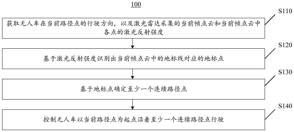
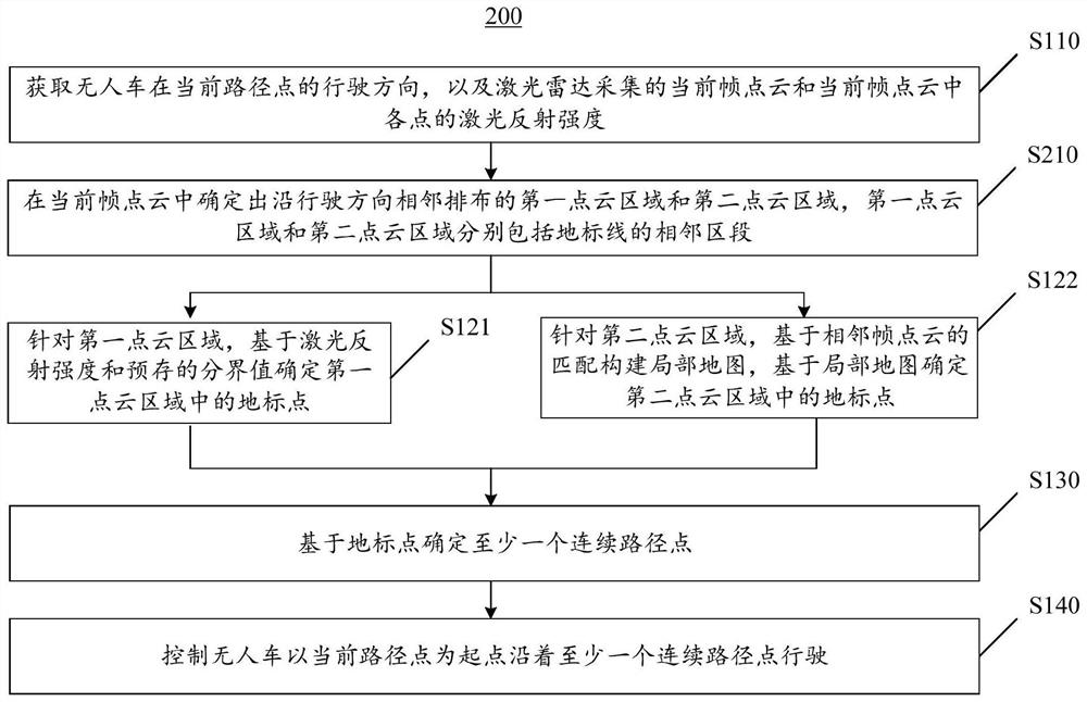
[0033] As mentioned in the background art, the autonomous navigation method of the unmanned vehicle for farm work is usually based on images, and this type of navigation method has the problems that it is easy to fail at the corners, the speed is constant, and the speed cannot be too fast. In order to solve the above problems, the present application provides a real-time navigation method and device based on lidar, an unmanned vehicle, a computer device, and a storage medium, which are used for the unmanned vehicle equipped with lidar on the ground where the landmark line is laid. Driving along the landmark line, the laser reflection intensity of the landmark line is smaller than the laser reflection intensity of the ground. The real-time navigation method includes: collecting the point cloud of the current frame and the laser reflection intensity of each point by using a laser radar, identifying landmark points from the point cloud of the current frame based on the laser reflection intensity, determining at least one continuous path point based on the landmark points, and controlling no People and vehicles travel along at least one consecutive waypoint.
[0034] According to the in-field real-time navigation method and device, computer equipment, and storage medium provided by the embodiments of the present application, since the point cloud collected by the lidar has geographic location information, which is a true reflection of the current environment, on the one hand, based on the point cloud to determine The current waypoint obtained will not deviate too much from the driving direction of the previous waypoint, thus improving the driving stability and avoiding control failure; on the other hand, multiple consecutive waypoints can be determined based on the same frame of point cloud. , to avoid the process of determining the waypoint from limiting the speed of the vehicle; on the other hand, since the point cloud collected by the lidar has depth information, it can ensure that the next waypoint can be accurately determined even when the speed of the vehicle changes.
[0035] The laser radar-based real-time navigation method and device, unmanned vehicle, computer equipment, and storage medium provided by the present application will be described in detail below with reference to specific embodiments.
[0036] Exemplary method
[0037] figure 1 This is a schematic flowchart of the real-time navigation method based on lidar provided by the first embodiment of the present application. This embodiment can be applied to an unmanned vehicle equipped with a lidar, and is used to realize that the unmanned vehicle runs along the landmark line on the ground where the landmark line is laid, and the laser reflection intensity of the landmark line is smaller than that of the ground. . The landmark line mentioned here is, for example, a mulch film, and the corresponding ground is soil; for another example, if the ground is a cement surface, the corresponding landmark line can be a paint line. like figure 1 As shown, the real-time navigation method 100 includes the following steps:
[0038] In step S110, the driving direction of the unmanned vehicle at the current waypoint, the current frame point cloud collected by the lidar, and the laser reflection intensity of each point in the current frame point cloud are acquired.
[0039] The current waypoint is the point on the landmark line. When the unmanned vehicle is at the current waypoint, the lidar collects a frame of point cloud, that is, the current frame point cloud. The scanning range of lidar can be a circular area with the current waypoint as the center, or a fan-shaped area with the current waypoint as the center. Correspondingly, a frame of point cloud can be distributed in a circle with the current waypoint as the center. , or it can be distributed in a fan shape with the current path point as the center.
[0040] Step S120, identifying the landmark point corresponding to the landmark line in the point cloud of the current frame based on the laser reflection intensity.
[0041] After the lidar emits a laser beam, the received beam intensity is different according to the reflectivity of the object and the distance. The normalized reflection intensity can be obtained by normalizing the beam intensity according to the distance information. The laser reflection intensity mentioned in this article refers to the normalized reflection intensity.
[0042] Since there is a significant difference between the laser reflection intensity of the landmark line and the laser reflection intensity of the surrounding ground, the landmark point can be identified based on the difference of the laser reflection intensity of each point in the point cloud of the current frame. For example, compare the laser reflection intensity of each point in the point cloud of the current frame with the pre-stored boundary value, which is used to indicate the boundary value of the laser reflection intensity of the landmark point and the ground point. When the laser reflection intensity is less than the boundary value , it is determined as a landmark point; when the laser reflection intensity is greater than the cut-off value, it is determined as a ground point. The cutoff value can be obtained based on a preliminary test, and then pre-stored in the memory for calling in step S120.
[0043] Step S130, at least one continuous waypoint is determined based on the landmark point.
[0044] Specifically, first, the principal vectors of landmark points are determined. For example, a principal component analysis (Principalcomponents analysis, PCA) algorithm is used to calculate the principal vectors of landmark points. Second, the main vector is segmented by a predetermined length. For example, it is divided into a section every 0.5m. Next, the center of gravity of each section is determined as the respective waypoint of each section. In other embodiments, for each section, the path point corresponding to the point cloud of the current frame may be corrected by using the path point corresponding to the point cloud of at least one previous frame, so as to improve the accuracy of each path point.
[0045] Step S140, controlling the unmanned vehicle to drive along at least one continuous waypoint with the current waypoint as a starting point. This step can be implemented by conventional methods, which will not be described in detail here.
[0046] According to the real-time navigation method based on lidar provided by this application, the current frame point cloud and the laser reflection intensity of each point are collected by lidar, landmark points are identified from the current frame point cloud based on the laser reflection intensity, and at least one landmark point is determined based on the landmark points. Continuous waypoints, control the unmanned vehicle to drive along at least one continuous waypoint. Since the point cloud collected by lidar has geographic location information, which is a true reflection of the current environment, on the one hand, the current waypoint determined based on the point cloud will not deviate too much from the driving direction of the previous waypoint, so It improves the driving stability and avoids control failure; on the other hand, multiple continuous waypoints can be determined based on the same frame of point cloud, avoiding the process of determining the waypoints from limiting the vehicle's driving speed; on the other hand, due to the laser The point cloud collected by the radar has depth information, which ensures that the next waypoint can be accurately determined even when the speed of the vehicle changes.
[0047] figure 2 This is a schematic flowchart of the real-time navigation method based on lidar provided by the second embodiment of the present application. exist figure 2 In the shown real-time navigation method 200, before step S120, it further includes:
[0048] Step S210, in the point cloud of the current frame, determine the first point cloud area and the second point cloud area that are adjacently arranged along the driving direction, and the first point cloud area and the second point cloud area respectively include adjacent landmarks. section.
[0049] In this case, step S120 is specifically executed as:
[0050] Step S121, for the first point cloud area, determine landmark points in the first point cloud area based on the laser reflection intensity and a pre-stored boundary value, where the boundary value refers to the boundary of the laser reflection intensity between the landmark point and the ground point corresponding to the ground value. Points with laser reflection intensity greater than the cut-off value are ground points, and points with laser reflection intensity less than the cut-off value are landmark points.
[0051] Step S122, for the second point cloud area, construct a local map based on the matching of adjacent frame point clouds, and determine landmark points in the second point cloud area based on the local map.
[0052] It should be noted that the execution sequence of step S121 and step S122 are partially sequential, and step S121 and step S122 may be executed synchronously.
[0053] In this case, step S130 may be specifically performed as: determining at least one first waypoint based on landmark points in the first point cloud area, determining at least one second waypoint based on landmark points in the second point cloud area, A first waypoint and at least one second waypoint are defined as a plurality of consecutive waypoints.
[0054] In step S210, the first point cloud area and the second point cloud area are located in the driving direction of the current waypoint, and the first point cloud area is an area extending in the driving direction starting from the current waypoint. The second point cloud area is another area formed by further extending in the driving direction on the basis of the first point cloud area. The point cloud density of the first point cloud area is greater than that of the second point cloud area, and different strategies are subsequently used to determine the path points for the first point cloud area and the second point cloud area. The shapes of the first point cloud area and the second point cloud area can be reasonably set according to the actual situation. The width of the first point cloud area and the second point cloud area perpendicular to the driving direction is greater than the width of the landmark line, and the lengths of the first point cloud area and the second point cloud area in the driving direction can be reasonably set according to actual needs. The density of the point clouds in the first point cloud area and the second point cloud area meets the positioning requirements.
[0055] Figures 3a-3c A schematic diagram of a process of determining a first point cloud area and a second point cloud area based on a point cloud of a current frame provided by an embodiment of the present application. like Figure 3a As shown, the point cloud of the current frame is distributed in a circle with the current path point O as the center of the circle. According to the different scanning ranges of the lidar, the point cloud of the current frame may include at least one column of landmark lines 10 . In this embodiment, step S210 is specifically executed as:
[0056] First, the current frame point cloud is divided into three parts by two concentric circles with the current path point O as the center, namely the circular area C in the center, the annular area R adjacent to the circular area C, and the annular area R Adjacent outer ring region D. Since the point cloud in the outer ring area D is too sparse, which is not conducive to determining the waypoints, the point cloud in the outer ring area D is filtered out, and the point clouds in the circular area C and the ring area R are retained. Among them, the radius of the concentric circles can be reasonably set according to the specific parameters of the lidar, so as to ensure that the density of the point clouds in the circular area C and the annular area R can meet the positioning accuracy requirements.
[0057] Second, see Figure 3b , in the point cloud of the current frame, determine the strip area S extending along the driving direction L with the driving direction L as the center line, and the width d of the strip area S 1 greater than the width d of the landmark line 10 2 and is less than the width d of the landmark line 10 2 and the interval d between the adjacent landmark line 10 3 2 times the sum of , that is, d 2 1 2 +2×d 3.
[0058] Next, continue to Figure 3b , the intersection area of the strip area S and the circular area C is determined as the first point cloud area C_r, and the intersection area of the strip area S and the annular area R is determined as the second point cloud area R_r, such as Figure 3c shown.
[0059] In this embodiment, based on the scanning rule of lidar, that is, the closer the distance to the lidar, the denser the point cloud collected, and the farther the distance from the lidar, the sparser the point cloud, and the first point cloud area is obtained. and the second point cloud area, the uniformity of the respective point cloud density of the first point cloud area and the second point cloud area is improved as much as possible.
[0060] In step S121, first, for each point in the first point cloud region C_r, the average value of the laser reflection intensity of the point set composed of the point and its surrounding points is determined. The point set mentioned here can be composed of the current point and its surrounding 8 neighbor points, for example. Secondly, the points corresponding to the point set whose average value is less than the cutoff value are determined as landmark points. The above process is repeated until each point in the first point cloud region C_r is traversed, so as to identify all landmark points in the first point cloud region C_r.
[0061] In step S122, since the point cloud of the second point cloud region R_r is sparser than that of the first point cloud region C_r, this embodiment determines the path for the second point cloud region R_r by constructing a local map points to improve the accuracy of the waypoints.
[0062] Specifically, first, a local map is constructed based on the matching of adjacent frame point clouds.
[0063] For example, see Figure 3c, using simultaneous localization and mapping (SLAM) technology to construct a local map based on the matching of adjacent frame point clouds.
[0064] Secondly, the boundary value of the laser reflection intensity is determined based on the statistical law of the laser reflection intensity of each point in the local map, and the boundary value refers to the boundary value of the laser reflection intensity of the landmark point and the ground point.
[0065] For example, divide the local map into multiple grids; build a histogram based on point clouds in multiple grids, the abscissa of the histogram is the laser reflection intensity, and the ordinate is the number of points; determine the coverage of the histogram on the abscissa The predetermined point in the interval is the boundary value of the reflection intensity, and the predetermined point is, for example, the midpoint. In one embodiment, before constructing the histogram, the variance of the laser reflection intensities of all points included in each of the multiple grids may also be calculated first; the variance is filtered based on a preset variance interval to filter out grids with uneven distribution grid; a histogram is then constructed based on the filtered grid.
[0066] Next, a point on the local map where the laser reflection intensity is greater than the cutoff value is determined as a landmark point.
[0067] So far, for the first point cloud area C_r and the second point cloud area R_r, different strategies are used to determine the landmark points included in their respective ranges. Subsequently, at least one continuous waypoint can be determined from the landmark points according to step S130.
[0068] According to the real-time navigation method provided in this embodiment, based on the scanning rule of lidar, that is, the closer the distance to the lidar is, the denser the point cloud is, and the farther the distance from the lidar is, the sparser the point cloud is. The path in front of the waypoint is divided into the first point cloud area and the second point cloud area. The point cloud density of the first point cloud area is greater than that of the second point cloud area. For the first point cloud area and the second point cloud area Different strategies are used to identify the mulching points, thereby improving the accuracy of the waypoints.
[0069] Figure 4 This is a schematic flowchart of the real-time navigation method based on lidar provided by the third embodiment of the present application. Figure 5 A schematic diagram of a waypoint determined based on a point cloud of a current frame provided by an embodiment of the present application. like Figure 4 As shown, in the real-time navigation method 300 shown in this embodiment, step S130 in the real-time navigation method 200 is specifically implemented as:
[0070] Step S131, determining at least one continuous first path point based on the principal vector of the landmark points in the first point cloud area.
[0071] Step S132, determining at least one continuous second path point based on the principal vector of the landmark points in the second point cloud area.
[0072] Step S133, based on the first N first path points corresponding to the current frame point cloud and at least one frame point cloud before the current frame point cloud in the first path point or the first path point corresponding to the predetermined area where the first N first path points are respectively located. Two waypoints determine N consecutive waypoints, and the number of N depends on the relationship between the driving speed of the unmanned vehicle and the scanning interval of the lidar.
[0073] Specifically, see Figure 5 , in step S131 , first, the PCA algorithm is used to calculate the principal vector of the landmark points in the first point cloud region C_r. Second, the main vector is segmented according to a predetermined length. For example, along the travel direction L of the current waypoint O, the first point cloud area C_r is divided into a section every 0.5m to obtain two first sections. The predetermined length of 0.5m given here is only an example, and can be adjusted reasonably according to the actual situation. Next, the center of gravity of each section is determined as the first way point P of each section 1. Among them, the center of gravity of the point cloud is a point coordinate, and calculating the center of gravity of the point cloud is equivalent to calculating the average value of the positions of all points in the cloud.
[0074] In step S132, first, the PCA algorithm is used to calculate the principal vector of the landmark points in the second point cloud region R_r. Second, the main vector is segmented according to a predetermined length. For example, along the travel direction L of the current waypoint O, the second point cloud region R_r is divided into a section every 0.5m to obtain two first sections. The predetermined length of 0.5m given here is only an example, and can be adjusted reasonably according to the actual situation. Next, the center of gravity of each section is determined as the second path point P of each section 2.
[0075] It should be noted that, before and after the execution sequence of step S131 and step S132, step S131 and step S132 may be executed synchronously.
[0076] Executed for each frame point cloud Figure 4 The steps S110 to S132 shown can all obtain at least one first path point P 1 (t i ) and at least one second waypoint P 2 (t i ), i represents the sequence number of the point cloud frame collected by the lidar.
[0077] Image 6 This is a flowchart of step S133 provided by an embodiment of the present application. like Image 6 As shown, step S133 includes:
[0078] Step S1331, for each first waypoint in the first N first waypoints, determine the mean value and sum of the first waypoints formed by at least one frame of point cloud before the current frame point cloud in the predetermined area where the first waypoint is located. The mean of the second waypoint.
[0079] Step S1332: Determine the weight based on the difference between the mean value of the first waypoint and the mean value of the second waypoint.
[0080] Step S1333: Perform weighting processing on the first waypoint based on the weight to obtain a waypoint corresponding to the first waypoint. In this case, any waypoint can be expressed as:
[0081]
[0082] Among them, k is the preset weight; i is the number of the point cloud frame collected by the lidar, n is the number of the point cloud of the current frame; m is the number of the waypoint.
[0083] The following is a combination of specific examples of Image 6 The implementation process is described in detail.
[0084] Figure 7 This is a schematic diagram of a first waypoint and a second waypoint determined by each of four consecutive point cloud frames provided in an embodiment of the present application. like Figure 7 As shown, in this embodiment, the unmanned vehicle is at the starting waypoint, that is, the first waypoint O 1 When the lidar collects the first frame of point cloud, two first path points P are determined based on the first frame of point cloud. 1 (t 1 ) and a second waypoint P 2 (t 1 ). In this situation, Figure 7 The shown waypoint of the first section 21 is the first waypoint P 1 (t 1 ), that is, the second way point O 2 , the unmanned vehicle travels from the first path point O 1 Drive autonomously to the second waypoint O 2. When the unmanned vehicle reaches the second waypoint O 2 When the lidar collects the second frame of point cloud, two first path points P are determined based on the second frame of point cloud. 1 (t 2 ) and a second waypoint P 2 (t 2 ). In this situation, Figure 7 The waypoint of the second section 22 is shown, ie the third waypoint The unmanned vehicle from the second waypoint O 2 Drive autonomously to the third waypoint O 3 When the lidar collects the third frame point cloud, two first path points P are determined based on the third frame point cloud. 1 (t 3 ) and a second waypoint P 2 (t 3 ). In this situation, Figure 7 The waypoint of the third section 23 shown is the fourth waypoint where k is the preset weight. So on and so forth.
[0085] It can be seen from the above process that, in this embodiment, the lidar collects one frame of point cloud at each waypoint. In this case, the waypoint of the next predetermined section can be uniquely determined based on each frame of point cloud.
[0086] In one embodiment, the first waypoint and the second waypoint determined based on the point cloud of the current frame and the point cloud of the previous frame are used to determine the waypoint at the next moment. Point clouds of two adjacent frames. In this situation, Figure 7 The waypoint of the third section 23 shown, the fourth waypoint Lidar at the fourth waypoint O 4 The fourth frame point cloud is collected, and two first path points P are determined based on the fourth frame point cloud. 1 (t 4 ) and a second waypoint P 2 (t 4 ). In this situation, Image 6 The waypoint of the fourth section 24 is shown, ie the fifth waypoint So on and so forth.
[0087] Figure 8 This is a schematic diagram of a first waypoint and a second waypoint respectively determined by three consecutive point cloud frames according to another embodiment of the present application. like Figure 8 As shown, in this embodiment, the unmanned vehicle is at the starting waypoint, that is, the first waypoint O 1 When the lidar collects the first frame of point cloud, two first path points P are determined based on the first frame of point cloud. 1 (t 1 ) and a second waypoint P 2 (t 1 ). In this situation, Figure 8 The shown way point of the first section 31 is the first way point P 1 (t 1 ), that is, the second way point O 2 , Figure 8 The illustrated waypoint of the second section 32 is the first waypoint P 1 (t 1 ), that is, the third way point O 3 , the unmanned vehicle travels from the first path point O 1 Drive autonomously to the second waypoint O 2 , and then from the second path point O 2 Drive autonomously to the third waypoint O 3. When the unmanned vehicle reaches the third waypoint O 3 When the lidar collects the second frame of point cloud, two first path points P are determined based on the second frame of point cloud. 1 (t 2 ) and a second waypoint P 2 (t 2 ). In this situation, Figure 8 The waypoint of the third section 33 shown, i.e. the fourth waypoint is denoted as: O 4 =k×[p 1 (t 2 )-p 2 (t 1 )]+p 2 (t 1 ). Figure 8 The waypoint of the fourth section 34 shown, ie the fifth waypoint is P 1 (t 2 ). The unmanned vehicle from the third waypoint O 3 Drive autonomously to the fourth waypoint O 4 , and then from the fourth path point O 4Drive autonomously to the fifth waypoint O 5. The unmanned vehicle is at the fifth waypoint O 5 When the lidar collects the third frame point cloud, two first path points P are determined based on the third frame point cloud. 1 (t 3 ) and a second waypoint P 2 (t 3 ). In this situation, Figure 8 The waypoint of the fifth section 35 shown, namely the sixth waypoint O 6 =k×[p 2 (t 2 )-p 1 (t 3 )]+p 1 (t 3 ), where k is the preset weight. So on and so forth.
[0088] It can be seen from the above process that in this embodiment, the lidar collects one frame of point cloud every time the unmanned vehicle walks through two predetermined road sections. In this case, the next two predetermined road segments can be determined based on each frame of point cloud The waypoint of the segment, that is, the next 2 consecutive waypoints are determined at the same time. By analogy, for example, when the unmanned vehicle travels through three predetermined road sections, when the lidar collects a frame of point cloud, the waypoints for the next three sections can be determined based on each frame of point cloud.
[0089] Exemplary device
[0090] The present application also provides a real-time navigation device based on lidar. Figure 9 This is a structural block diagram of a real-time navigation device based on lidar provided by an embodiment of the present application. like Figure 9 As shown, the real-time navigation device 40 based on lidar is suitable for an unmanned vehicle equipped with lidar, and is used to control the unmanned vehicle to drive along the landmark line on the ground with the landmark line, and the laser reflection of the landmark line The intensity is less than that of the laser reflection from the ground. The real-time navigation device 40 includes an acquisition module 41 , an identification module 42 , a determination module 43 and a control module 44 . The obtaining module 41 is used to obtain the driving direction of the unmanned vehicle at the current waypoint, the current frame point cloud collected by the lidar, and the laser reflection intensity of each point in the current frame point cloud. The identification module 42 is configured to identify the landmark point corresponding to the landmark line in the point cloud of the current frame based on the laser reflection intensity. A determination module 43 is used to determine at least one continuous waypoint based on the landmark points. The control module 44 is configured to control the unmanned vehicle to drive along at least one continuous waypoint starting from the current waypoint.
[0091] According to the real-time navigation device based on lidar provided by the present application, the current frame point cloud and the laser reflection intensity of each point are collected by lidar, landmark points are identified from the current frame point cloud based on the laser reflection intensity, and at least one landmark point is determined based on the landmark points. Continuous waypoints, control the unmanned vehicle to drive along at least one continuous waypoint. Since the point cloud collected by lidar has geographic location information, which is a true reflection of the current environment, on the one hand, the current waypoint determined based on the point cloud will not deviate too much from the driving direction of the previous waypoint, so It improves the driving stability and avoids control failure; on the other hand, multiple continuous waypoints can be determined based on the same frame of point cloud, avoiding the process of determining the waypoints from limiting the vehicle's driving speed; on the other hand, due to the laser The point cloud collected by the radar has depth information, which ensures that the next waypoint can be accurately determined even when the speed of the vehicle changes.
[0092] Figure 10 This is a structural block diagram of a real-time navigation device based on lidar provided by another embodiment of the present application. like Figure 10 As shown, the real-time navigation device 50 is Figure 9 The shown real-time navigation device 50 further includes a partition module 51 for determining the first point cloud area and the second point cloud area adjacent to the driving direction in the point cloud of the current frame, the first point cloud area and the second point cloud region respectively include adjacent segments of the landmark line.
[0093] In one embodiment, the partitioning module 51 is specifically configured to: divide the point cloud of the current frame by using two concentric circles with the current path point as the center to obtain a circular area and an annular area adjacent to the circular area; In the frame point cloud, determine the strip area extending along the driving direction with the driving direction as the center line, and the width of the strip area is greater than the width of the landmark line; the intersection area of the strip area and the circular area is determined as the first point cloud area; The intersection area of the bar area and the ring area is determined as the second point cloud area.
[0094] In this case, the identification module 42 includes a first identification unit 421 and a second identification unit 422 . The first identification unit 421 is configured to, for the first point cloud area, determine the landmark point in the first point cloud area based on the laser reflection intensity and a pre-stored boundary value, where the boundary value refers to the laser beam between the landmark point and the corresponding ground point on the ground. The cutoff value for reflection intensity. The second identifying unit 422 is configured to, for the second point cloud area, construct a local map based on the matching of point clouds of adjacent frames, and determine landmark points in the second point cloud area based on the local map.
[0095] In one embodiment, the first identification unit 421 is specifically configured to, for each point in the first point cloud region, determine the average value of the laser reflection intensity of the point set composed of the point and its surrounding points; The point corresponding to the point set whose value is less than the cutoff value is determined as the landmark point.
[0096] In one embodiment, the second identification unit 422 is specifically configured to, for the second point cloud area, construct a local map based on the matching of point clouds of adjacent frames; determine the laser reflection intensity based on the statistical law of the laser reflection intensity of each point in the local map The boundary value refers to the boundary value of the laser reflection intensity between the landmark point and the corresponding ground point on the ground; the point on the local map whose laser reflection intensity is less than the boundary value is determined as the landmark point.
[0097] In one embodiment, as Figure 10 As shown, the determination module 43 includes a first determination unit 431 , a second determination unit 432 and a third determination unit 434 . The first determining unit 431 is configured to determine at least one continuous first path point based on the principal vector of the landmark point in the first point cloud region. The second determining unit 432 is configured to determine at least one continuous second waypoint based on the principal vectors of the landmark points in the second point cloud area. The third determining unit 434 is configured to, based on the first N first waypoints corresponding to the point cloud of the current frame and the point cloud of at least one frame before the point cloud of the current frame, corresponding to the first N first waypoints in the respective predetermined areas. The waypoint or the second waypoint determines N consecutive waypoints, where N is a positive integer, and the number of N depends on the relationship between the driving speed of the unmanned vehicle and the scanning interval of the lidar.
[0098] The first determining unit 431 is specifically configured to determine the main vector of the landmark points in the first point cloud area; divide the main vector into segments according to a predetermined length; and determine the center of gravity of each segment as the respective first path point of each segment. The second determining unit 432 is specifically configured to determine the continuous at least one second path point based on the main vector of the landmark point in the second point cloud area, which includes: determining the main vector of the landmark point in the second point cloud area; The main vector is divided into segments; the center of gravity of each segment is determined as the respective second waypoint of each segment. The third determining unit 434 is specifically configured to, for each of the first N first waypoints, determine the first point cloud formed by at least one frame of point cloud before the current frame of point cloud in the predetermined area where the first waypoint is located. The mean value of the waypoint and the mean value of the second waypoint; the weight is determined based on the difference between the mean value of the first waypoint and the mean value of the second waypoint; the weighting process is performed on the first waypoint based on the weight, and the corresponding value of the first waypoint is obtained. waypoint.
[0099] The real-time navigation device based on lidar provided by this embodiment belongs to the same concept of the application as the real-time navigation method based on lidar provided by the embodiment of the present application, and can execute the real-time navigation method based on lidar provided by any embodiment of the present application , with corresponding functional modules and beneficial effects for implementing the real-time navigation method based on lidar. For technical details that are not described in detail in this embodiment, reference may be made to the real-time navigation method based on lidar provided by this embodiment of the present application, which will not be repeated here.
[0100] unmanned vehicle
[0101] The application also provides an unmanned vehicle, the structural block diagram of which is as follows: Figure 11 shown. see Figure 11 , the unmanned vehicle 60 is adapted to drive along the plastic film in the field where the plastic film is laid. The unmanned vehicle 60 includes a lidar 61, a processor 62 and a controller 63. The laser radar 61 is used to obtain the point cloud of the current frame and the laser reflection intensity of each point in the point cloud of the current frame. The processor 62 is configured to obtain the driving direction of the unmanned vehicle at the current waypoint; identify the landmark point corresponding to the landmark line in the point cloud of the current frame based on the laser reflection intensity; based on the landmark point Identify at least one consecutive waypoint. The controller 63 is configured to control the unmanned vehicle to drive along the at least one continuous waypoint starting from the current waypoint. The processor 62 may execute the laser radar-based real-time navigation method provided by any embodiment of the present application. For details, refer to the above-mentioned embodiments of the laser-radar-based real-time navigation method, which will not be repeated here.
[0102] Exemplary Electronics
[0103] Figure 12 It is a structural block diagram of an electronic device provided by an exemplary embodiment of the present application. This electronic device can be integrated in an unmanned vehicle. like Figure 12 As shown, electronic device 70 includes one or more processors 71 and memory 72.
[0104] Processor 71 may be a central processing unit (CPU) or other form of processing unit having data processing capabilities and/or instruction execution capabilities, and may control other components in electronic device 70 to perform desired functions.
[0105] Memory 72 may include one or more computer program products, which may include various forms of computer-readable storage media, such as volatile memory and/or non-volatile memory. Volatile memory may include, for example, random access memory (RAM) and/or cache memory, among others. Non-volatile memory may include, for example, read only memory (ROM), hard disk, flash memory, and the like. One or more computer program instructions may be stored on the computer-readable storage medium, and the processor 71 may execute the program instructions to implement the LiDAR-based real-time navigation method and/or the various embodiments of the present application described above. or other desired functionality. Various contents such as point cloud data, laser reflection intensity, etc. may also be stored in the computer-readable storage medium.
[0106] In one example, the electronic device 70 may also include an input device 73 and an output device 74 interconnected by a bus system and/or other form of connection mechanism (not shown).
[0107] For example, the input device 73 may be a lidar for collecting point cloud data of the current environment. When the electronic device is a stand-alone device, the input device 73 may be a communication network connector for receiving signals from a wireless network. In addition, the input device 73 may also include, for example, a keyboard, a mouse, and the like.
[0108] The output device 74 can output various information to the outside, including the position information of the N consecutive waypoints determined. Output devices 74 may include, for example, displays, speakers, printers, and communication networks and their connected remote output devices, among others.
[0109] Of course, for simplicity, Figure 12 Only some of the components of the electronic device 70 that are relevant to the present application are shown in FIG. 1 , and components such as buses, input/output interfaces, and the like are omitted. Besides, the electronic device 70 may also include any other suitable components according to the specific application.
[0110] Exemplary computer program product and computer readable storage medium
[0111] In addition to the above-described methods and apparatus, embodiments of the present application may also be computer program products comprising computer program instructions that, when executed by a processor, cause the processor to perform the methods described in the "Exemplary Methods" section of this specification above. Steps in an in-field real-time navigation method according to various embodiments of the present application.
[0112] The computer program product may be written in any combination of one or more programming languages to write program codes for performing the operations of the embodiments of the present application. The programming languages include object-oriented programming languages, such as Java, C++, etc., as well as conventional procedural programming language, such as "C" language or similar programming language. The program code may execute entirely on the user computing device, partly on the user device, as a stand-alone software package, partly on the user computing device and partly on a remote computing device, or entirely on the remote computing device or server execute on.
[0113] In addition, embodiments of the present application may also be computer-readable storage media having computer program instructions stored thereon that, when executed by the processor, cause the processor 71 to perform the processes described in the above-mentioned "Example Method" section of this specification. Steps in an in-field real-time navigation method according to various embodiments of the present application.
[0114] The computer-readable storage medium may employ any combination of one or more readable media. The readable medium may be a readable signal medium or a readable storage medium. The readable storage medium may include, for example, but not limited to, electrical, magnetic, optical, electromagnetic, infrared, or semiconductor systems, apparatuses or devices, or a combination of any of the above. More specific examples (non-exhaustive list) of readable storage media include: electrical connections with one or more wires, portable disks, hard disks, random access memory (RAM), read only memory (ROM), erasable programmable read only memory (EPROM or flash memory), optical fiber, portable compact disk read only memory (CD-ROM), optical storage devices, magnetic storage devices, or any suitable combination of the foregoing.
[0115] The basic principles of the present application have been described above in conjunction with specific embodiments. However, it should be pointed out that the advantages, advantages, effects, etc. mentioned in the present application are only examples rather than limitations, and these advantages, advantages, effects, etc., are not considered to be Required for each embodiment of this application. In addition, the specific details disclosed above are only for the purpose of example and easy understanding, rather than limiting, and the above-mentioned details do not limit the application to be implemented by using the above-mentioned specific details.
[0116] The block diagrams of devices, apparatus, apparatuses, and systems referred to in this application are merely illustrative examples and are not intended to require or imply that the connections, arrangements, or configurations must be in the manner shown in the block diagrams. As those skilled in the art will appreciate, these means, apparatuses, apparatuses, systems may be connected, arranged, configured in any manner. Words such as "including", "including", "having" and the like are open-ended words meaning "including but not limited to" and are used interchangeably therewith. As used herein, the words "or" and "and" refer to and are used interchangeably with the word "and/or" unless the context clearly dictates otherwise. As used herein, the word "such as" refers to and is used interchangeably with the phrase "such as but not limited to".
[0117] It should also be pointed out that in the apparatus, equipment and method of the present application, each component or each step can be decomposed and/or recombined. These disaggregations and/or recombinations should be considered as equivalents of the present application.
[0118] The above description of the disclosed aspects is provided to enable any person skilled in the art to make or use this application. Various modifications to these aspects will be readily apparent to those skilled in the art, and the generic principles defined herein may be applied to other aspects without departing from the scope of the application. Therefore, this application is not intended to be limited to the aspects shown herein but is to be accorded the widest scope consistent with the principles and novel features disclosed herein.
[0119] The foregoing description has been presented for the purposes of illustration and description. Furthermore, this description is not intended to limit the embodiments of the application to the forms disclosed herein. Although a number of example aspects and embodiments have been discussed above, those skilled in the art will recognize certain variations, modifications, changes, additions and sub-combinations thereof.
PUM


Description & Claims & Application Information
We can also present the details of the Description, Claims and Application information to help users get a comprehensive understanding of the technical details of the patent, such as background art, summary of invention, brief description of drawings, description of embodiments, and other original content. On the other hand, users can also determine the specific scope of protection of the technology through the list of claims; as well as understand the changes in the life cycle of the technology with the presentation of the patent timeline. Login to view more.
Similar technology patents
Stamping equipment applied to motor rotor punching sheet production
Owner:SHENGZHOU LIDA ELECTRIC APPLIANCES FACTORY
Method for recycling manganese ion in electrolytic manganese production tail end wastewater
Owner:CHINESE RES ACAD OF ENVIRONMENTAL SCI
Passivating agent for weakly acidic cadmium contaminated soil and application thereof
Owner:NANJING UNIV
Coverage rate test processing method and device and coverage rate test server and system
Owner:ALIBABA GRP HLDG LTD
Classification and recommendation of technical efficacy words
- Improve stability
- avoid control failure
Gel stabilized nanoparticulate active agent compositions
Owner:ALKERMES PHARMA IRELAND LTD
Method for preparing silica aerogel material
Owner:中科润资科技股份有限公司
Compositions and methods for protein design
Owner:CODON DEVICES
Gas dielectric structure forming methods
Owner:GLOBALFOUNDRIES INC
Household appliance control method, household appliance control system and wearable device
PendingCN112965391Aachieve effective controlavoid control failure
Owner:QINGDAO HAIER AIR CONDITIONER GENERAL CORP LTD +2
Input method of Android application on Linux platform
Owner:北京麟卓信息科技有限公司