
Power transformer capable of preventing snow accumulation

A technology for power transformers and transformers, applied in the field of transformers, can solve problems such as affecting the normal use of transformers, and achieve the effects of accelerating melting speed, avoiding excessive water accumulation, and improving service life.

Active Publication Date: 2022-05-27
南通西东电器有限公司
View PDF6 Cites 2 Cited by
  • Summary
  • Abstract
  • Description
  • Claims
  • Application Information

AI Technical Summary

Problems solved by technology

[0004] Some current power transformers only use some shell top covers to protect themselves, and in snowy weather, the surface of the shell top cover will accumulate more snow for a long time, which will affect the normal use of the transformer itself , and it is impossible to automatically deal with snow accumulation

Method used


Image

  • Power transformer capable of preventing snow accumulation
  • Power transformer capable of preventing snow accumulation
  • Power transformer capable of preventing snow accumulation

Examples


Embodiment 1

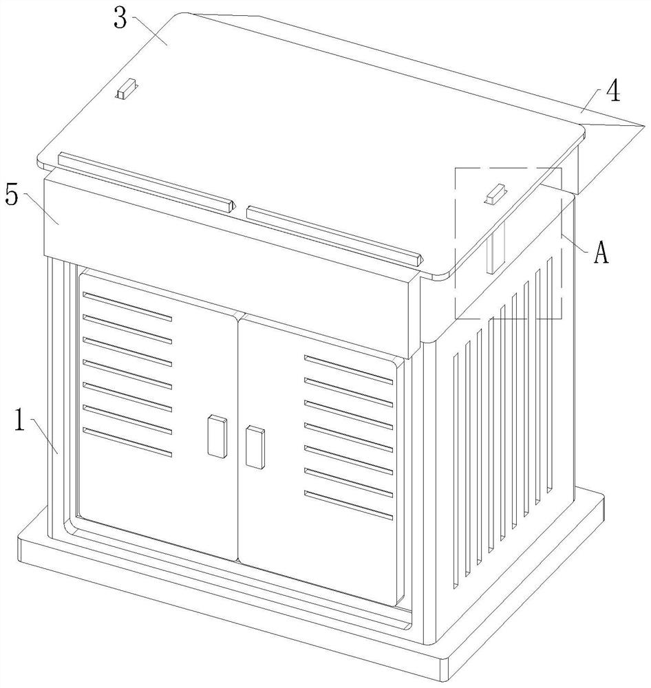
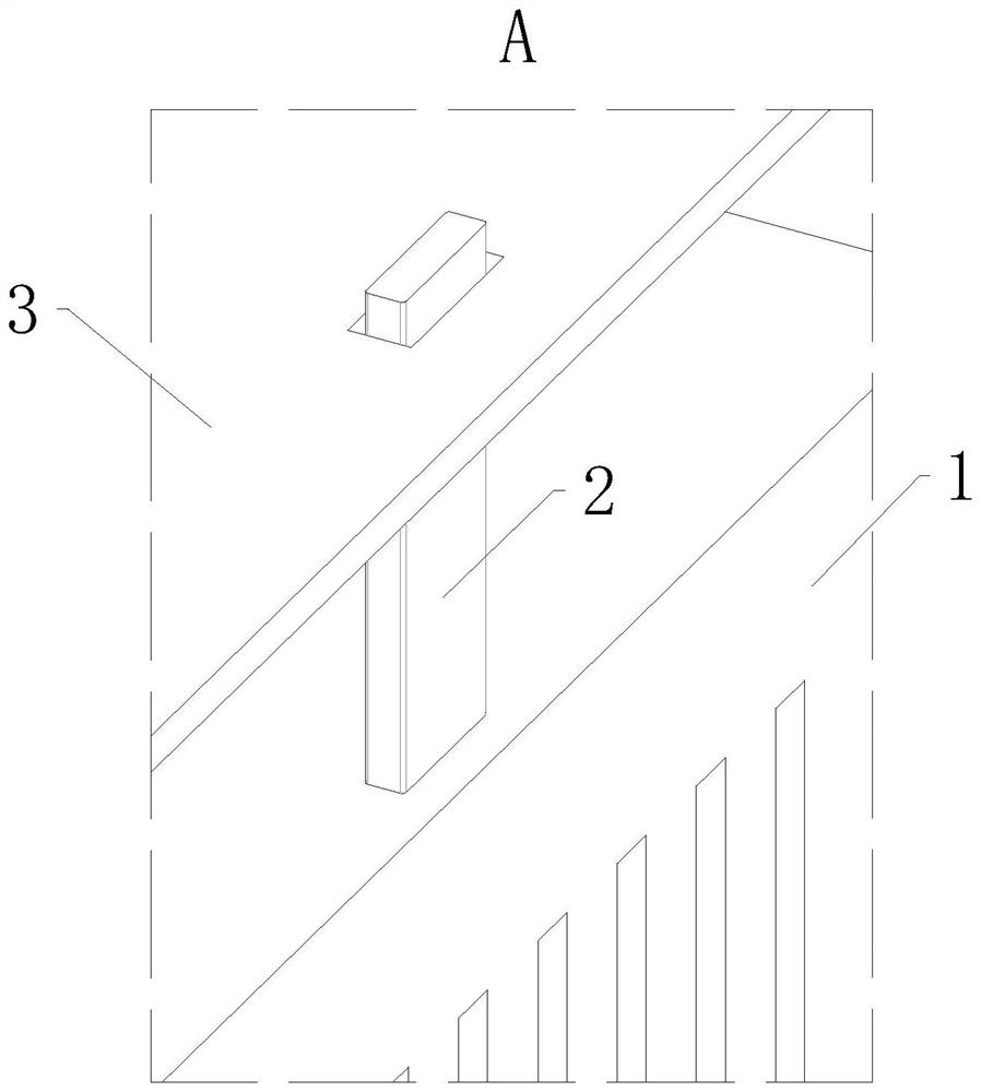
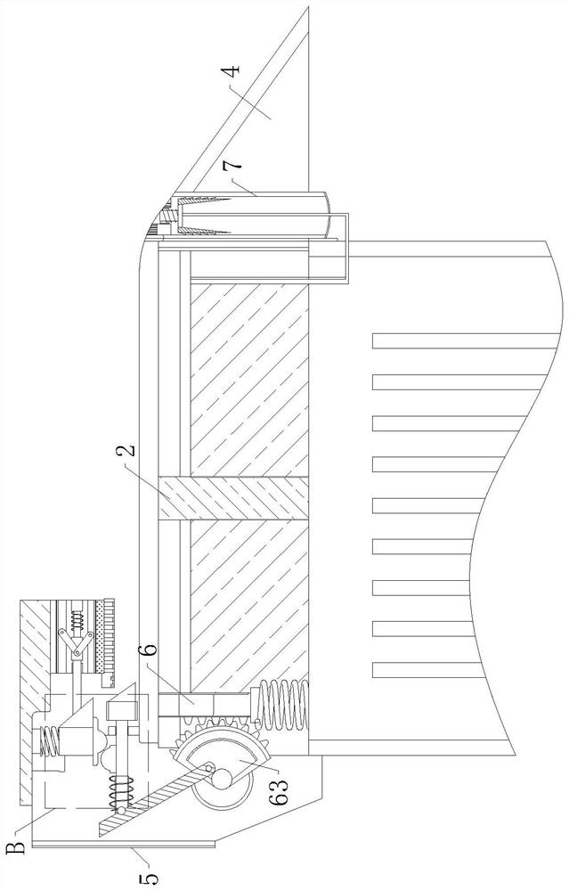
[0030] like Figure 1 to Figure 7As shown in the figure, a power transformer for preventing heavy snow accumulation according to the embodiment of the present invention includes a transformer body 1, and through rods 2 are fixedly connected to both sides of the upper end surface of the transformer body 1. The upper part of the transformer body 1 and the A receiving plate 3 is slidably connected to the outer surface of the through rod 2 , a tilting seat 4 is fixedly connected to the side surface of the transformer body 1 and located at the rear side of the receiving plate 3 , and a mounting plate 4 is fixedly connected to the front surface of the transformer body 1 . Frame 5, the lower end surface of the receiving plate 3 is provided with a cleaning mechanism 6, and the inside of the inclined seat 4 is fixedly connected with a circulation pipe 7; The outer surface moves, and the snow can be cleaned automatically by the cleaning mechanism 6 .

[0031] like image 3 and Image...

Embodiment 2

[0036] like Figure 8 As shown in the comparison example 1, another embodiment of the present invention is: the inside of the circulation pipe 7 is movably connected with a pull rod 71, the outer surface of the pull rod 71 is provided with a pull spring 72, and the lower end of the pull rod 71 is provided with a pull rod 71. A crushing rod 73 is fixedly connected to the left and right sides of the tie rod, a water inlet pipe 74 is fixedly connected to the inside of the circulation pipe 7, a U-shaped rod 75 is fixedly connected to the lower end of the tie rod 71, and both ends of the U-shaped rod 75 are fixedly connected. They are respectively connected with the lower surface of the tie rod 71 and the lower surface of the receiving plate 3, and a plurality of limit pipes are arranged inside the water inlet pipe 74; during operation, some rainwater formed by snow will flow to the surface of the receiving plate 3 through the surface of the receiving plate 3. one side of the incli...


PUM


Abstract

The invention belongs to the field of transformers, and particularly relates to a heavy snow accumulation prevention power transformer which comprises a transformer body, penetrating rods are fixedly connected to the two sides of the upper end face of the transformer body, and a bearing plate is slidably connected to the position, above the transformer body, of the outer surfaces of the penetrating rods; and an inclined seat is fixedly connected to the side surface of the transformer body and located on the rear side of the bearing plate, a mounting frame is fixedly connected to the front surface of the transformer body, and a cleaning mechanism is arranged on the lower end face of the bearing plate. A compression spring is changed into an extension state from a compression state, a telescopic rod and a cleaning rod are driven to move at a high speed, the cleaning rod automatically treats accumulated snow on the surface of a bearing plate, the accumulated snow can be automatically cleaned according to the gravity of the accumulated snow, the phenomenon that normal use of a transformer is affected by too much accumulated snow is avoided, and the safety of the transformer is improved. And meanwhile, the device can be suitable for various severe environments.

Description

technical field [0001] The invention belongs to the field of transformers, in particular to a power transformer for preventing heavy snow accumulation. Background technique [0002] The transformer is a device that uses the principle of electromagnetic induction to change the AC voltage. The main components are the primary coil, the secondary coil and the iron core. The main functions are voltage transformation, current transformation, impedance transformation, isolation and voltage regulation. Transformers can convert electrical energy into It is converted into high voltage and low current form, and then converted back, thus greatly reducing the loss of electric energy in the process of transmission. [0003] In order to ensure that the power transformer can be applied to various environments, some solutions have also been proposed in the prior art. For example, a Chinese patent with publication number CN204102665U discloses a snow-proof, ice-proof, and freeze-proof transfo...

Claims


Application Information

Patent Timeline
Patent Type & Authority Applications(China)
IPC IPC(8): H01F27/00B08B1/00
CPCH01F27/00B08B1/10B08B1/30Y02A30/14
Inventor 葛海平
Owner 南通西东电器有限公司
Learn More