
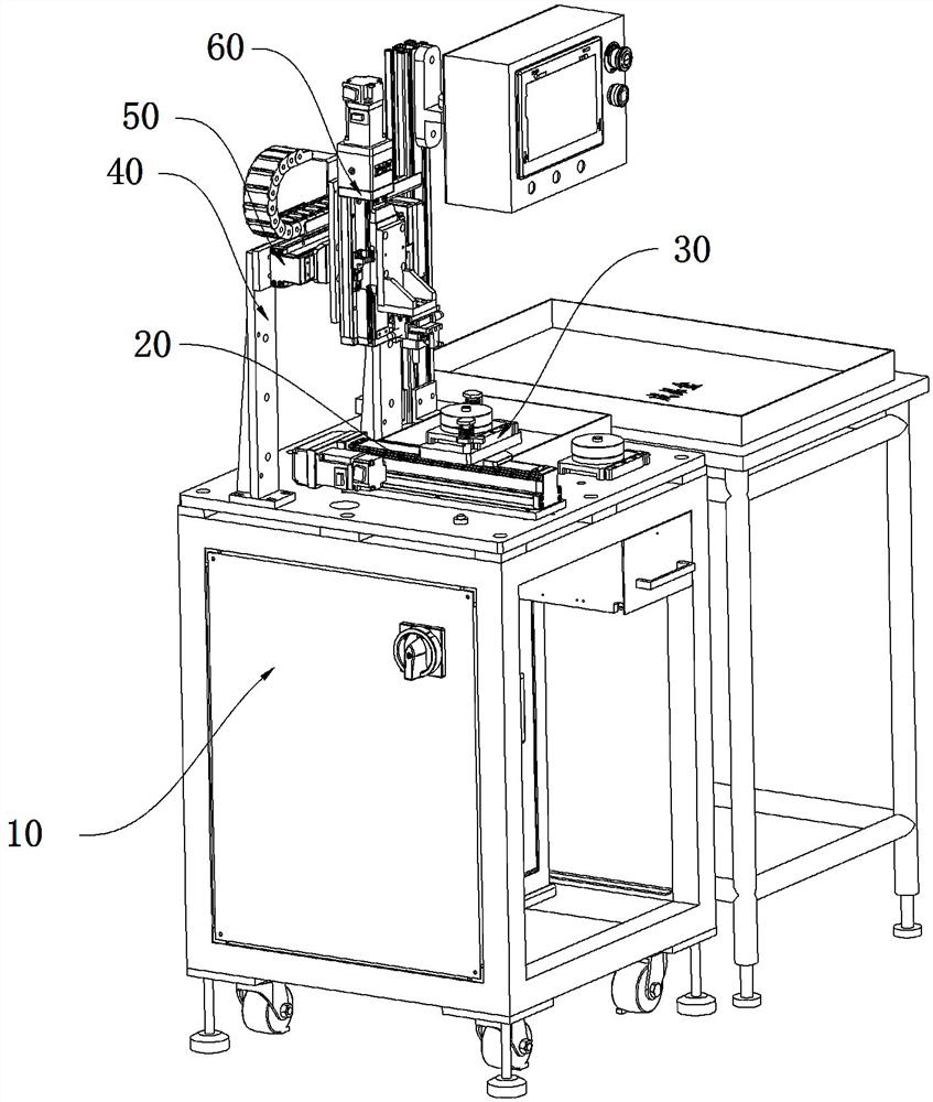
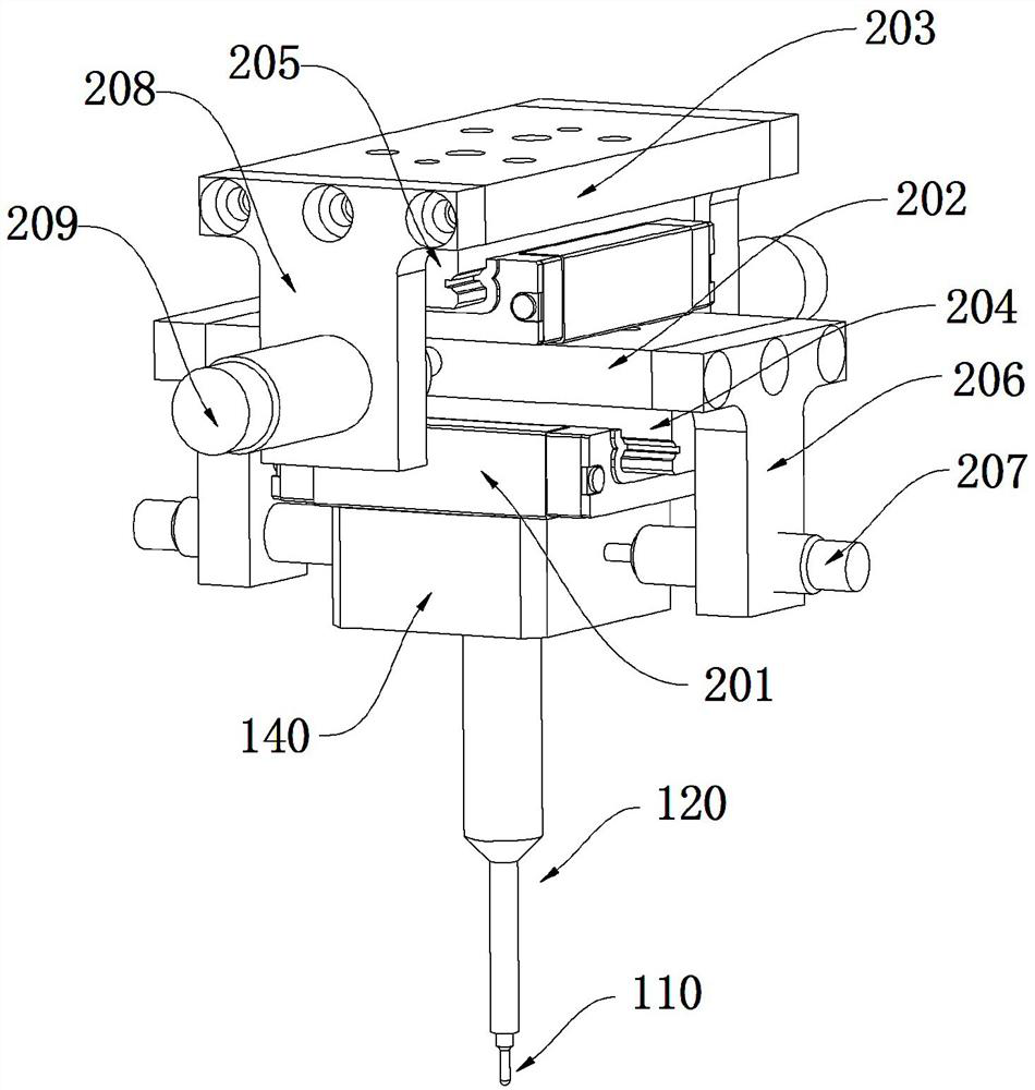
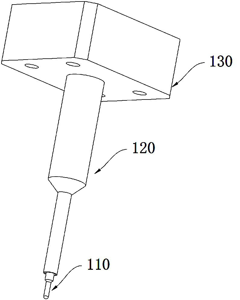
Riveting assembly and connector contact riveting device

A technology of riveting and components, which is applied in the assembly/disassembly of contact parts, etc., can solve the problems of dimensional error, short service life of tooling, and many knocking times, so as to ensure service life, avoid rigid contact, and ensure riveting pressure The effect of precision

Pending Publication Date: 2022-05-27
SICHUAN HUAFENG ENTERPRISE GRP
View PDF0 Cites 0 Cited by
  • Summary
  • Abstract
  • Description
  • Claims
  • Application Information

AI Technical Summary

Problems solved by technology

[0003] a. The striking force of the artificial hammer is not uniform enough, and the riveting finished product is prone to misalignment and offset;
[0004] b. At present, manual riveting, product consistency and quality are highly affected by human factors, and the overall efficiency is low;
[0005] c. It needs to be aligned once every time it is tapped, and the number of taps is large, and the labor intensity is high;
[0006] Moreover, during the riveting process, the connector contacts need to be clamped by tooling, which is formed by injection molding. Due to the low accuracy of injection molding, the clamping accuracy of the connector contacts is not high. There are multiple parts, in the process of automatic riveting, there will be superposition of dimensional errors, which will affect the riveting accuracy of some rivets, and even cause damage to the connector contacts in severe cases, and the connector contact clips formed by injection molding There will be wear and tear during the use of the tooling, which will lead to a short service life of the tooling and need to be replaced regularly, resulting in increased costs. After the tooling is worn out, it will further affect the clamping accuracy of the connector contact parts

Method used


Image

  • Riveting assembly and connector contact riveting device
  • Riveting assembly and connector contact riveting device
  • Riveting assembly and connector contact riveting device

Examples


Embodiment Construction

[0028] In order to make the purposes, technical solutions and advantages of the embodiments of the present invention clearer, the technical solutions in the embodiments of the present invention will be clearly and completely described below with reference to the accompanying drawings in the embodiments of the present invention. Obviously, the described embodiments These are some embodiments of the present invention, but not all of them. The components of the embodiments of the invention generally described and illustrated in the drawings herein may be arranged and designed in a variety of different configurations.

[0029] Thus, the following detailed description of the embodiments of the invention provided in the accompanying drawings is not intended to limit the scope of the invention as claimed, but is merely representative of selected embodiments of the invention. Based on the embodiments of the present invention, all other embodiments obtained by those of ordinary skill i...


PUM


Abstract

The riveting assembly comprises a positioning pin, a riveting piece, a fixing piece and a buffering assembly capable of achieving radial buffering, the riveting piece is axially installed on the fixing piece in a floating mode, the positioning pin is axially installed in the riveting piece in a floating mode, the bottom of the positioning pin axially penetrates out of the bottom of the riveting piece, and the fixing piece is installed at the bottom of the buffering assembly. The invention further discloses a connector contact riveting device. The riveting head is provided with the positioning needle, accurate alignment of the riveting piece and the riveting sleeve is achieved, the riveting precision is guaranteed, the buffering assembly is arranged, the riveting head has flexible floating, even if small deviation exists in riveting alignment, the riveting head can be subjected to floating adjustment and has position compensation, and the riveting precision is guaranteed. And in the next riveting process, the riveting head can be reset, so that the accurate positioning of the positioning needle and each corresponding contact element can be realized, the automatic continuous riveting of the riveting sleeve is realized, the riveting precision is ensured, and the consistency of products is good.

Description

technical field [0001] The invention relates to the technical field of connector riveting, in particular to a riveting assembly and a connector contact riveting device. Background technique [0002] At present, the contacts and rivet sleeves in the connector are manually riveted. The manual assembly process is as follows: manually insert the contacts and rivet sleeves into the insulating plate, and tap the riveting head with a hammer to rive the riveting sleeve into the contact parts. This riveting method has the following disadvantages: [0003] a. The knocking force of the artificial hammer is not uniform enough, and the riveted finished product is prone to dislocation and deviation; [0004] b. At present, artificial riveting, product consistency and quality are highly affected by human factors, and the overall efficiency is low; [0005] c. Each tap needs to be aligned once, the number of taps is large, and the labor intensity is high; [0006] Moreover, during the ri...

Claims


Application Information

Patent Timeline
Patent Type & Authority Applications(China)
IPC IPC(8): H01R43/20
CPCH01R43/20Y02E60/10
Inventor 周松霖唐波
Owner SICHUAN HUAFENG ENTERPRISE GRP
Learn More