
Eureka
For R&D, Eureka makes reading and utilizing patents & technical documents easy.
Eureka AIR
Designed for self-driven R&D workflows. Generate viable solutions, solve complex R&D challenges, empower your innovation with AI.

Eureka Materials
Designed for material experts only. Revolutionize your material R&D, from search, analyze, to developing new materials.

TechResearch
Generate reliable direction feasibility study reports for your R&D in just a few steps.

TechSeek
Discover and master advanced knowledge NOW. Basics, ideas, possibilities, all at once.

TechMind
As an expert in R&D Theories, TechMind can generates customized viable solutions instantly.

TechRisk
Analyze your overall solution with one click, know your potential R&D risks in advance.

TechMonitor
Get weekly tech updates, stay abreast of the latest tech innovations and key insights.
Device and method for using abrasive belt in continuously running abrasive belt grinding machine in laterally precisely defined manner
A guiding device and abrasive belt technology, which is applied to abrasive belt grinders, grinders, and machine tools suitable for grinding workpiece planes, etc., can solve problems such as uneconomical, unsuitable for practical application, and unachievable output.
- Summary
- Abstract
- Description
- Claims
- Application Information
AI Technical Summary
Problems solved by technology
Method used
Image

Examples
Embodiment Construction
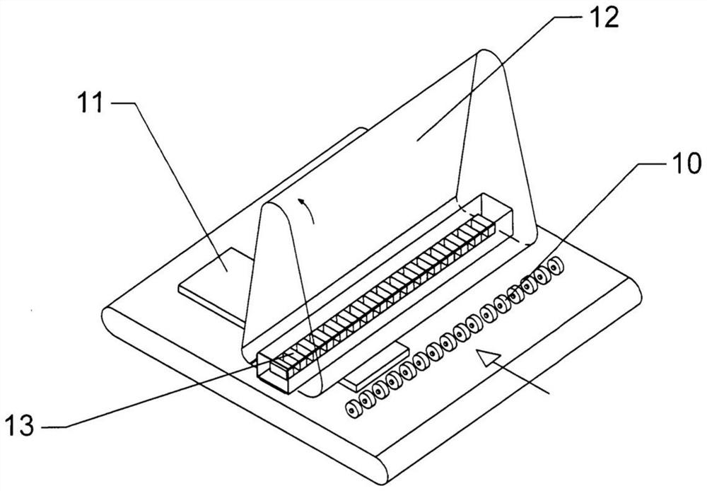
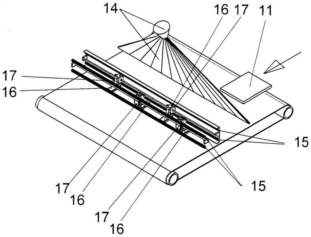
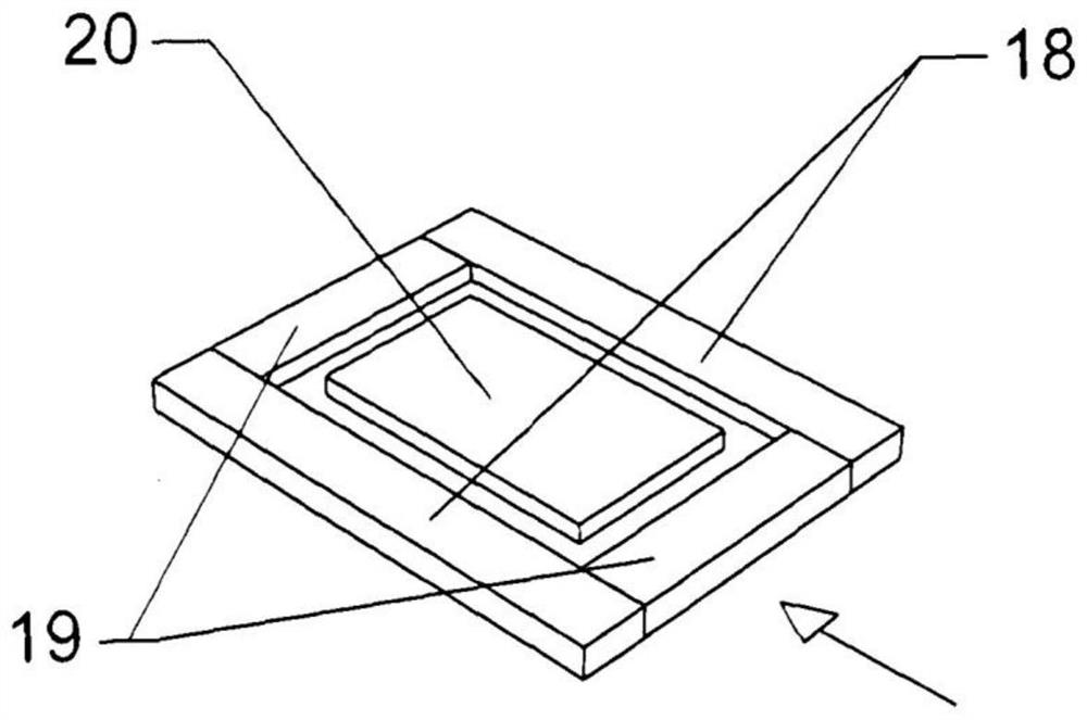
[0013] In use by the present invention described, in Figure 1When the apparatus shown in, the workpiece (11) at its side edge through the detector (14), such as a camera or laser device to detect. The control apparatus, by means of linear motion, such as a servo motor (17) and a lead screw, places the moving pressure device (16) on the guide device (15) in the corresponding lateral position and controls its use. The possible deviations from the right angle entry relative to the workpiece (11) are compensated for in the control technology. Pressure devices with precise lateral movement are particularly used for grinding frames with longitudinal straps (18) and transverse straps (19). After pre-lateral grinding of the entire frame, the longitudinal strap (18) is precisely positioned, so that finally for all the straps, the grinding direction is consistent with the direction of the wood fibers. If the filler (20) inside the frame is also to be ground together, a movable pressure devi...
PUM
 Abstract
Description
Claims
Application Information
 - R&D Engineer
- R&D Manager
- IP Professional
- Industry Leading Data Capabilities
- Powerful AI technology
- Patent DNA Extraction
Browse by: Latest US Patents, China's latest patents, Technical Efficacy Thesaurus, Application Domain, Technology Topic, Popular Technical Reports.
© 2024 PatSnap. All rights reserved.Legal|Privacy policy|Modern Slavery Act Transparency Statement|Sitemap|About US| Contact US: help@patsnap.com