Method and system for buck converter current reuse

A voltage converter, current technology, applied in control/regulation systems, high-efficiency power electronic conversion, output power conversion devices, etc., can solve problems such as runaway and output voltage rise

Pending Publication Date: 2022-05-27
TEXAS INSTR INC
View PDF0 Cites 0 Cited by
  • Summary
  • Abstract
  • Description
  • Claims
  • Application Information

AI Technical Summary

Problems solved by technology

This can create a situation where energy is constantly being stored without being dissipated by the load, causing the output voltage to keep rising to a runaway condition

Method used


Image

  • Method and system for buck converter current reuse
  • Method and system for buck converter current reuse
  • Method and system for buck converter current reuse

Examples


Embodiment Construction

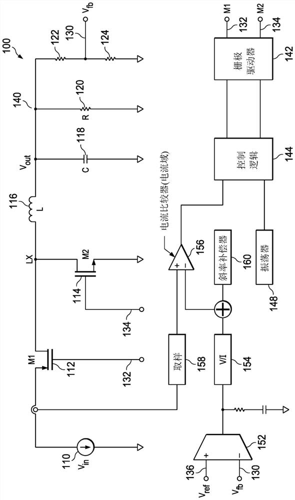
[0019] figure 1 An example DC / DC step-down converter is illustrated. The buck converter includes an input voltage source 110 which may be a battery or some other type of DC power source. In one embodiment, a typical voltage range of the input voltage source may be from 2.2V to 4.9V. An input voltage source 110 is coupled to the source of a PMOS transistor 112 which is a high-side switch. The drain of transistor 112 is coupled to one terminal of inductor 116 and to the drain of low-side switch NMOS transistor 114 , the source of which is electrically connected to ground. The gates of 112 and 114 are controlled by output signals 132 and 134 of gate driver circuit 142, respectively. The other terminal of the inductor 116 is coupled to one terminal of a capacitor 118 , the other terminal of which is electrically connected to ground.

[0020] The buck converter load is represented by load resistor 120 . The buck converter can be voltage controlled, current controlled, or a com...


PUM


Abstract

A buck voltage converter includes a high side switch (412), a low side switch (414), a capacitor (418), an inductor (416), a gate driver circuit (342) having an output coupled to a gate terminal of the high side switch (412) and a gate terminal of the low side switch (414), and a separate voltage regulator circuit to power circuitry (430) inside the buck voltage converter. The voltage regulator circuit includes a multiplexer (440) having a first multiplexer input (390) coupled to an input voltage source, a second multiplexer input (392) coupled to a buck output of the buck voltage converter, and one or more multiplexer control inputs to select which one of the two multiplexer inputs (390, 392) is to be coupled to the multiplexer output; and a pass transistor (446) having a first terminal coupled to the multiplexer output of the multiplexer and having a second terminal coupled to a regulator output (480) of the voltage regulator.

Description

Background technique [0001] A buck converter is a DC / DC power converter that steps up or steps down the voltage between its input from a main power supply and its output while stepping up the current. Buck converters are used in circuits where the DC output voltage needs to be lower than the DC input voltage. A buck converter is a switch-mode power supply that typically includes at least two semiconductors, which may be two transistors, making up a high-side switch coupled to a supply voltage and a low-side switch coupled to ground. The buck converter also includes at least one energy storage element, which may be a capacitor or an inductor, or a combination of both, which stores energy during high-side conduction and discharges during low-side conduction. [0002] When the high-side transistor is on, current flows through the load via the inductor. The inductor's response is to resist changes in current flow and store energy. A switching transistor between the input node a...

Claims


Application Information

Patent Timeline
Patent Type & Authority Applications(China)
IPC IPC(8): H02M3/00
CPCG05F1/565H02M1/32H02M1/0054H02M1/0032H02M1/0006H02M1/0045H02M3/1588H02M3/157Y02B70/10H02M3/158H02M1/0016
Inventor S·迪耶特里克C·哈德E·乔兰
Owner TEXAS INSTR INC
Why Eureka
Try Eureka