Clinical operation auxiliary device for obstetrics and gynecology department

An auxiliary device, obstetrics and gynecology technology, used in surgery, operating table, massage auxiliary products, etc., can solve the problems of inability to move legs at any time, poor blood flow, etc., to relieve poor blood circulation in the legs, promote The effect of blood circulation

Inactive Publication Date: 2022-05-31
ZHENGZHOU CENT HOSPITAL
View PDF0 Cites 0 Cited by
  • Summary
  • Abstract
  • Description
  • Claims
  • Application Information

AI Technical Summary

Problems solved by technology

But when the operation time is too long, the bracket used to raise the patient's legs usually acts on a certain fixed part of the patient's leg, and during the operation, this position will always be pressed, and because the patient is in a coma, The legs cannot be moved at any time, so the legs are in a state of long-term compression, which may easily cause poor blood flow and cause serious consequences. Based on the above problems, an auxiliary device for clinical operations in obstetrics and gynecology is proposed.

Method used


Image

  • Clinical operation auxiliary device for obstetrics and gynecology department
  • Clinical operation auxiliary device for obstetrics and gynecology department
  • Clinical operation auxiliary device for obstetrics and gynecology department

Examples


Embodiment 1

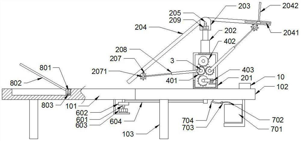
[0043] like Figure 1-3 As shown, an auxiliary device for clinical operation in obstetrics and gynecology, comprising a support bed;

[0044] Two leg support brackets, located at the two ends of the upper side of the support bed, respectively, the leg support brackets include:

[0045] The box body 201, the bottom of which is slidably connected to the upper surface of the supporting bed;

[0046] The bottom end of the electric telescopic support rod 202 is fixedly connected with the upper surface of the box body 201;

[0047] The mounting seat 203 is located on the top of the electric telescopic support rod 202;

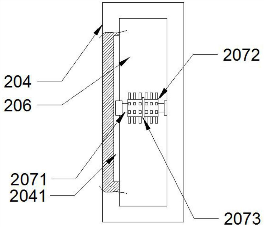
[0048] Two U-shaped plates 204 are respectively arranged on both sides of the mounting seat 203, one of the U-shaped plates 204 is distributed at a certain angle with the upper surface of the supporting bed, and is fixedly connected with the mounting seat 203, and the other U-shaped plate 204 be fixedly connected with the first adjusting shaft 205 arranged on the ...

Embodiment 2

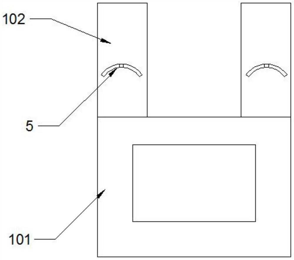
[0065] like Figure 1-3 As shown, the supporting bed body includes a bed board 101. Mounting boards 102 are respectively provided on both sides of one end of the bed board 101. The bed board 101 and the bottom of the mounting board 102 are provided with support rods 103 respectively. A mounting plate forms the support for the operating table.

[0066] The two mounting plates 102 are respectively provided with arc-shaped through grooves 5, and the slider provided at the bottom of the box body 201 is slidably connected with the arc-shaped through grooves 5. The two mounting plates 102 are used to install two legs for placing the patient's legs. External support frame.

[0067] The bottom of the bed board 101 is provided with two rotating shafts 601 whose tops are rotatably connected to the bottom of the bed board 101 respectively. One of the rotating shafts 601 is connected to the output shaft of the angle adjusting motor 603 provided on the bed board 101 in a driving connectio...

Embodiment 3

[0072] like Figure 1-3 As shown, both ends of the first adjusting shaft 205 are respectively connected to the mounting seat 203 for rotation, and one end of the first adjusting shaft 205 is engaged and drivingly connected with the output shaft of the first adjusting motor 209 provided on the mounting seat 203 . The rotation of the first adjustment motor 209 is controlled to control the rotation of the first adjustment shaft 205, so as to realize the rotation of the U-shaped plate 204 fixedly connected with the first adjustment shaft 205, and the calf of the patient fixed on the U-shaped plate 204 rotates. Controlling the rotation of the patient's calf can also alleviate the problem of poor blood circulation in the leg caused by the long-term operation to a certain extent.


PUM


Abstract

The invention discloses an auxiliary device for clinical operations in the obstetrics and gynecology department. The auxiliary device comprises a supporting bed body; the two leg supporting frames are located at the two ends of one side above the supporting bed body respectively, each leg supporting frame comprises a box body, and the bottom of each leg supporting frame is in sliding connection with the upper surface of the supporting bed body; the bottom end of the electric telescopic supporting rod is fixedly connected with the upper surface of the box body; the mounting seat is positioned at the top of the electric telescopic supporting rod; a first through groove is formed in the bottom of each U-shaped plate, a massage roller is arranged in each first through groove, and the two ends of each massage roller are slidably connected with the inner walls of the two sides of the corresponding first through groove. The two U-shaped plates are used for fixing thighs and shanks of a patient, the two massage rotating shafts and the driving mechanism used for driving the two massage rotating shafts to rotate in a reciprocating mode are arranged in the box body, and the massage rotating shafts are connected with the massage rollers through the telescopic rods; the massage roller can slide back and forth along the first through groove in the U-shaped plate to massage the legs of the patient, and blood circulation of the legs of the patient is promoted.

Description

technical field [0001] The invention relates to the technical field of obstetrics and gynecology surgical equipment, in particular to an auxiliary device for obstetrics and gynecology clinical surgery. Background technique [0002] In the process of treating obstetrics and gynecology diseases, surgery is often required, and during the surgical treatment, the patient's legs need to be elevated, so as to facilitate the operation by the doctor. However, when the operation time is too long, the bracket used to raise the patient's legs usually acts on a fixed part of the patient's leg, and during the operation, this position will always be compressed. At the same time, because the patient is in a coma, It is impossible to move both legs at any time, so the legs are in a state of long-term compression, which may easily cause poor blood flow and cause serious consequences. Based on the above problems, an auxiliary device for clinical surgery in obstetrics and gynecology is proposed...

Claims


Application Information

Patent Timeline
Patent Type & Authority Applications(China)
IPC IPC(8): A61G13/08A61G13/10A61G13/12A61H15/00A61M35/00
CPCA61G13/08A61G13/10A61G13/1245A61H15/0078A61M35/20A61H2201/0142A61H2201/1207A61H2201/1642
Inventor 李艳敏王淑丽
Owner ZHENGZHOU CENT HOSPITAL
Why Eureka
Try Eureka