Miniature transformer manufacturing multi-station assembly equipment

A micro-transformer and assembly equipment technology, applied in the field of transformer manufacturing, can solve the problems of increasing labor costs, shell deformation, time-consuming and laborious, etc., and achieve the effect of solving high labor costs, avoiding shell deformation, and improving assembly efficiency.

Inactive Publication Date: 2022-05-31
徐州彤宇自动化科技有限公司
View PDF0 Cites 1 Cited by
  • Summary
  • Abstract
  • Description
  • Claims
  • Application Information

AI Technical Summary

Problems solved by technology

[0003] In the existing micro-transformer manufacturing process, the coil is usually wound and formed first, and then the formed coil is placed on several stacked iron cores. Finally, in order to ensure the stability of the iron core and coil and facilitate installation and fixation The outer side of the iron core is sheathed with an iron shell, which will cause the following problems: 1. The formed coil is set on the iron core and then packaged by manual operation. In order to keep the shell and the iron core Closely connected, the size of the shell and the iron core will generally be relatively close. In the process of manually setting the shell, due to the small gap between the shell and the iron core, there will be a large friction between the two. At this time The operator needs to use a lot of force to insert the iron core into the casing, and the casing is generally provided with an integrally formed compression piece. When the iron core is inserted into the casing, the compression piece needs to be bent to fix the iron core. This process Generally, it is manually operated. This assembly method is time-consuming and labor-intensive, which increases labor costs. At the same time, it is easy to deform the shell during the process of pressing the iron core into the shell. This situation increases the difficulty of assembly between the iron core and the shell. , which reduces the assembly efficiency of the micro-transformer; 2. The existing micro-transformer assembly is generally a single-station operation, and a single operator can only assemble a single micro-transformer at the same time, and this assembly method is not efficient

Method used


Image

  • Miniature transformer manufacturing multi-station assembly equipment
  • Miniature transformer manufacturing multi-station assembly equipment
  • Miniature transformer manufacturing multi-station assembly equipment

Examples


Embodiment Construction

[0030] In order to make the technical means, creative features, goals and effects achieved by the present invention easy to understand, the present invention will be further described below in conjunction with specific illustrations. It should be noted that, in the case of no conflict, the embodiments in the present application and the features in the embodiments can be combined with each other.

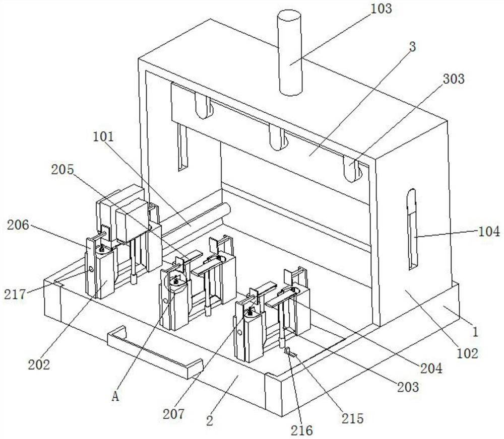
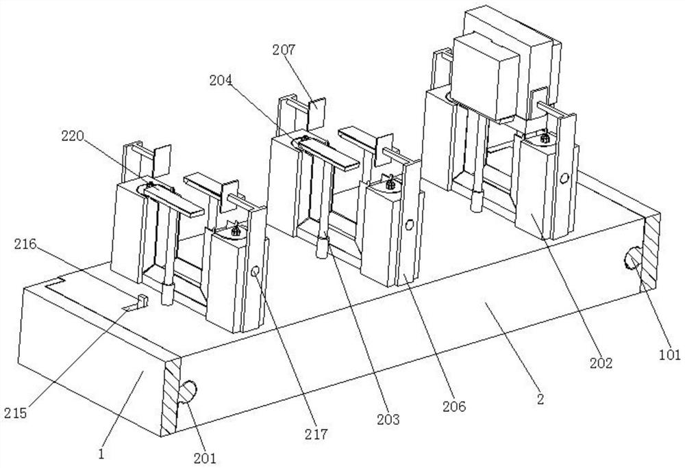
[0031] refer to figure 1 and image 3 , a kind of miniature transformer manufacturing multi-station assembly equipment, comprises fixed base 1, and fixed base 1 is U-shaped structure, and the inner wall of fixed base 1 is fixedly installed with two mutually symmetrical guide rails 101, between two guide rails 101 There is an operating platform 2 between them, and both sides of the operating platform 2 are provided with connecting chute 201, and the two connecting chute 201 are connected with the corresponding guide rails 101 respectively, and the operating platform 2 is slidably ins...


PUM


Abstract

The invention relates to the field of transformer manufacturing, in particular to miniature transformer manufacturing multi-station assembly equipment which comprises a fixed base, the fixed base is of a U-shaped structure, two guide rails which are symmetrically arranged are fixedly installed on the inner wall of the fixed base, and an operation platform is arranged between the two guide rails. Connecting sliding grooves are formed in the two sides of the operation platform correspondingly, and the two connecting sliding grooves are connected with the correspondingly-arranged guide rails in an inserted mode correspondingly. When an existing miniature transformer is assembled, due to the fact that a gap between a shell and an iron core is small, large friction force can be generated between the shell and the iron core, at the moment, an operator needs to use large force to insert the iron core into the shell, and the assembling mode wastes time and labor. According to the miniature transformer, the iron core and the shell can be quickly and conveniently inserted and fixed, quick packaging can be achieved, the problem that the labor cost is high in the assembling process of an existing miniature transformer is solved, and the assembling efficiency of the miniature transformer is improved.

Description

technical field [0001] The invention relates to the field of transformer manufacturing, in particular to a multi-station assembly equipment for manufacturing micro transformers. Background technique [0002] Miniature transformers generally refer to a transformer with a small size and low power. It is generally used for electrical control of electrical equipment. The manufacturing cost of this kind of transformer is generally low, and it is mainly composed of coils and iron cores. [0003] In the existing micro-transformer manufacturing process, the coil is usually wound and formed first, and then the formed coil is placed on several stacked iron cores. Finally, in order to ensure the stability of the iron core and coil and facilitate installation and fixation The outer side of the iron core is sheathed with an iron shell, which will cause the following problems: 1. The formed coil is set on the iron core and then packaged by manual operation. In order to keep the shell and ...

Claims


Application Information

Patent Timeline
IPC IPC(8): B23P19/027B25B11/02
CPCB23P19/027B25B11/02
Inventor 陈文志
Owner 徐州彤宇自动化科技有限公司
Why Eureka
Try Eureka